How to Use AS5047P: Examples, Pinouts, and Specs
Introduction
The AS5047P is a high-resolution magnetic rotary position sensor designed to provide precise angular position measurements. With a 14-bit resolution, it ensures accurate and reliable performance in demanding applications. The sensor uses a contactless magnetic measurement principle, making it robust against environmental factors such as dust, dirt, and oil. It supports SPI and PWM communication interfaces, offering flexibility for integration into various systems.
Explore Projects Built with AS5047P


Explore Projects Built with AS5047P
Common Applications and Use Cases
- Robotics: Joint position sensing and feedback
- Industrial automation: Motor shaft position monitoring
- Motor control: Brushless DC (BLDC) and stepper motor position sensing
- Automotive: Steering angle and throttle position sensing
- Consumer electronics: Precision control systems
Technical Specifications
Key Technical Details
| Parameter | Value |
|---|---|
| Resolution | 14-bit |
| Supply Voltage (VDD) | 3.3V or 5V |
| Current Consumption | 12 mA (typical) |
| Interface | SPI, PWM |
| Maximum Speed | 28,000 RPM |
| Operating Temperature | -40°C to +125°C |
| Magnetic Field Strength | 30 mT to 70 mT |
| Package | TSSOP-14 |
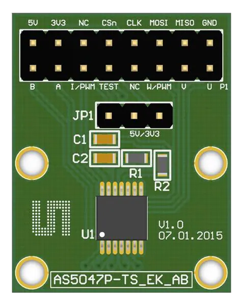
Pin Configuration and Descriptions
| Pin Number | Pin Name | Description |
|---|---|---|
| 1 | VDD3V3 | 3.3V power supply input |
| 2 | VDD5V | 5V power supply input |
| 3 | GND | Ground |
| 4 | CSn | Chip Select (active low) for SPI communication |
| 5 | CLK | SPI Clock input |
| 6 | MISO | SPI Master-In-Slave-Out (data output) |
| 7 | MOSI | SPI Master-Out-Slave-In (data input) |
| 8 | PWM | Pulse Width Modulation output for angular position |
| 9 | A | Incremental encoder A output |
| 10 | B | Incremental encoder B output |
| 11 | Index | Incremental encoder index pulse output |
| 12 | PROG | Programming pin for OTP (One-Time Programmable) memory |
| 13 | TEST | Test pin (leave unconnected in normal operation) |
| 14 | NC | Not connected |
Usage Instructions
How to Use the AS5047P in a Circuit
- Power Supply: Connect the VDD3V3 or VDD5V pin to a 3.3V or 5V power source, respectively, and connect the GND pin to the ground.
- Magnet Placement: Place a diametrically magnetized magnet above the sensor at a distance of 0.5 mm to 3 mm. Ensure the magnet is centered for accurate readings.
- Communication Interface:
- For SPI: Connect the CSn, CLK, MISO, and MOSI pins to the corresponding SPI pins on your microcontroller.
- For PWM: Use the PWM pin to read the angular position as a duty cycle.
- Incremental Encoder: Use the A, B, and Index pins if you need incremental encoder functionality.
- Programming: If required, use the PROG pin to program the OTP memory.
Important Considerations and Best Practices
- Ensure the magnetic field strength is within the specified range (30 mT to 70 mT) for accurate operation.
- Use decoupling capacitors (e.g., 100 nF) close to the power supply pins to reduce noise.
- Avoid placing ferromagnetic materials near the sensor, as they can distort the magnetic field.
- For high-speed applications, ensure the SPI clock frequency is configured correctly to avoid communication errors.
Example Code for Arduino UNO (SPI Interface)
#include <SPI.h>

// Define SPI pins for the AS5047P
const int CSn = 10; // Chip Select pin connected to Arduino pin 10

void setup() {
  // Initialize SPI communication
  SPI.begin();
  pinMode(CSn, OUTPUT);
  digitalWrite(CSn, HIGH); // Set CSn high to deselect the sensor

  Serial.begin(9600); // Initialize serial communication for debugging
}

uint16_t readAngle() {
  uint16_t angle = 0;

  // Start SPI communication with the AS5047P
  digitalWrite(CSn, LOW); // Select the sensor
  delayMicroseconds(1);   // Short delay for stability

  // Send the command to read the angle (0x3FFF is the angle register)
  uint16_t command = 0x3FFF;
  uint8_t highByte = SPI.transfer((command >> 8) & 0xFF); // Send high byte
  uint8_t lowByte = SPI.transfer(command & 0xFF);         // Send low byte

  // Combine the received bytes into a 14-bit angle value
  angle = ((highByte << 8) | lowByte) & 0x3FFF;

  digitalWrite(CSn, HIGH); // Deselect the sensor
  return angle;
}

void loop() {
  uint16_t angle = readAngle(); // Read the angular position
  float degrees = (angle * 360.0) / 16384.0; // Convert to degrees (14-bit resolution)

  Serial.print("Angle: ");
  Serial.print(degrees);
  Serial.println(" degrees");

  delay(100); // Wait 100 ms before the next reading
}
Troubleshooting and FAQs
Common Issues and Solutions
No Output or Incorrect Readings:
- Ensure the magnet is properly aligned and within the specified distance from the sensor.
- Verify the power supply voltage and connections.
- Check the SPI or PWM connections for loose or incorrect wiring.
Noise in Readings:
- Add decoupling capacitors near the power supply pins.
- Ensure the sensor is not exposed to strong external magnetic fields.
SPI Communication Fails:
- Verify the SPI clock frequency and ensure it is within the sensor's supported range.
- Check the CSn pin state during communication (it should be low when active).
PWM Output Not Detected:
- Ensure the PWM pin is connected to the correct input on your microcontroller.
- Verify the microcontroller's PWM reading configuration.
FAQs
Q: Can the AS5047P be used with a 5V microcontroller?
A: Yes, the AS5047P supports both 3.3V and 5V power supplies, making it compatible with 5V microcontrollers.
Q: What type of magnet should I use?
A: Use a diametrically magnetized magnet with a magnetic field strength of 30 mT to 70 mT.
Q: How do I calculate the angle from the PWM output?
A: Measure the duty cycle of the PWM signal. The angle is proportional to the duty cycle, where 0% corresponds to 0° and 100% corresponds to 360°.