How to Use ME60N03 4-Channel Mosfet: Examples, Pinouts, and Specs
Introduction
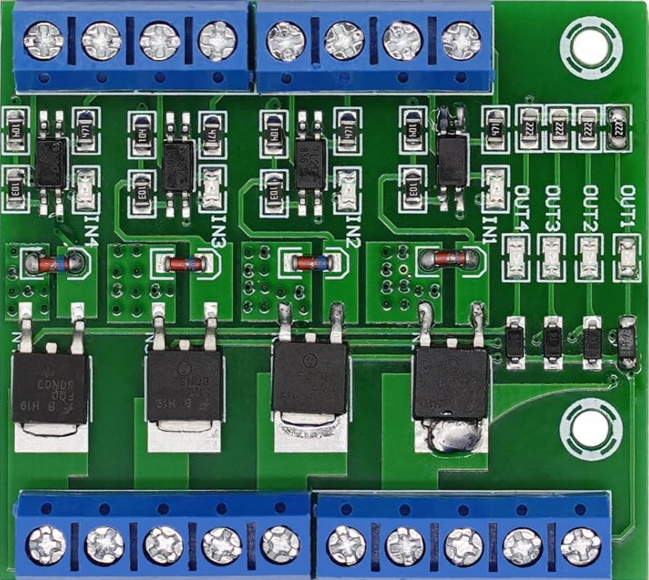
The ME60N03 4-Channel MOSFET is a high-performance, multi-channel MOSFET designed for efficient switching applications. It features four independent channels, making it ideal for controlling multiple loads simultaneously. With low on-resistance and fast switching speeds, this component is well-suited for applications requiring high efficiency and precise control.
Explore Projects Built with ME60N03 4-Channel Mosfet


Explore Projects Built with ME60N03 4-Channel Mosfet
Common Applications and Use Cases
- Motor control for robotics and automation
- LED lighting systems
- Power management in battery-operated devices
- DC-DC converters
- General-purpose switching in embedded systems
Technical Specifications
The following table outlines the key technical specifications of the ME60N03 4-Channel MOSFET:
| Parameter | Value |
|---|---|
| Manufacturer Part ID | ME60N03 4-Channel MOSFET |
| Channels | 4 |
| Maximum Drain-Source Voltage (VDS) | 30V |
| Maximum Gate-Source Voltage (VGS) | ±20V |
| Continuous Drain Current (ID) | 60A per channel (at 25°C) |
| On-Resistance (RDS(on)) | ≤ 0.02Ω (typical) |
| Maximum Power Dissipation | 50W |
| Switching Speed | Fast |
| Operating Temperature | -55°C to +150°C |
| Package Type | Multi-channel TO-220 or similar |
Pin Configuration and Descriptions
The ME60N03 4-Channel MOSFET has the following pin configuration:
| Pin Number | Pin Name | Description |
|---|---|---|
| 1 | Gate 1 | Gate terminal for Channel 1 |
| 2 | Drain 1 | Drain terminal for Channel 1 |
| 3 | Source 1 | Source terminal for Channel 1 |
| 4 | Gate 2 | Gate terminal for Channel 2 |
| 5 | Drain 2 | Drain terminal for Channel 2 |
| 6 | Source 2 | Source terminal for Channel 2 |
| 7 | Gate 3 | Gate terminal for Channel 3 |
| 8 | Drain 3 | Drain terminal for Channel 3 |
| 9 | Source 3 | Source terminal for Channel 3 |
| 10 | Gate 4 | Gate terminal for Channel 4 |
| 11 | Drain 4 | Drain terminal for Channel 4 |
| 12 | Source 4 | Source terminal for Channel 4 |
Usage Instructions
How to Use the ME60N03 in a Circuit
- Power Supply: Ensure the power supply voltage does not exceed the maximum drain-source voltage (30V).
- Gate Drive: Use a gate drive voltage within the range of ±20V. A typical logic-level signal (e.g., 5V or 3.3V) can be used for switching.
- Load Connection: Connect the load between the drain terminal and the positive supply voltage. The source terminal should be connected to ground.
- Gate Resistor: Use a small resistor (e.g., 10Ω) in series with the gate to limit inrush current and prevent oscillations.
- Heat Dissipation: Ensure proper heat dissipation using a heatsink or cooling mechanism, especially when operating at high currents.
Example Circuit with Arduino UNO
The following example demonstrates how to control an LED strip using one channel of the ME60N03 MOSFET and an Arduino UNO:
Circuit Connections
- Connect the Gate 1 pin to Arduino digital pin 9 through a 10Ω resistor.
- Connect the Drain 1 pin to the positive terminal of the LED strip.
- Connect the Source 1 pin to ground.
- Connect the negative terminal of the LED strip to ground.
- Ensure the power supply for the LED strip matches its voltage and current requirements.
Arduino Code
// Example code to control an LED strip using the ME60N03 MOSFET
// connected to Arduino digital pin 9.

const int mosfetGatePin = 9; // Pin connected to Gate 1 of the MOSFET

void setup() {
  pinMode(mosfetGatePin, OUTPUT); // Set the MOSFET gate pin as an output
}

void loop() {
  digitalWrite(mosfetGatePin, HIGH); // Turn on the LED strip
  delay(1000); // Keep it on for 1 second
  digitalWrite(mosfetGatePin, LOW);  // Turn off the LED strip
  delay(1000); // Keep it off for 1 second
}
Important Considerations and Best Practices
- Avoid Overvoltage: Ensure the drain-source and gate-source voltages do not exceed their maximum ratings.
- Gate Drive Voltage: Use a gate drive voltage appropriate for the MOSFET's threshold voltage to ensure proper switching.
- Thermal Management: Use a heatsink or active cooling if the MOSFET operates at high currents for extended periods.
- Parasitic Inductance: Minimize parasitic inductance in the circuit by keeping traces short and using proper decoupling capacitors.
Troubleshooting and FAQs
Common Issues and Solutions
MOSFET Overheating
- Cause: Insufficient heat dissipation or excessive current.
- Solution: Use a heatsink or active cooling. Ensure the current is within the rated limit.
Load Not Turning On
- Cause: Insufficient gate drive voltage or incorrect wiring.
- Solution: Verify the gate drive voltage is sufficient (e.g., 5V for logic-level operation). Check all connections.
MOSFET Not Switching Properly
- Cause: Gate resistor value too high or parasitic capacitance.
- Solution: Use a smaller gate resistor (e.g., 10Ω) and ensure proper PCB layout to minimize parasitic effects.
High Power Loss
- Cause: High on-resistance or improper switching.
- Solution: Verify the MOSFET is fully turned on by providing adequate gate voltage. Check for proper PWM signal if applicable.
FAQs
Q1: Can I use the ME60N03 MOSFET for AC loads?
A1: No, the ME60N03 is designed for DC applications only. For AC loads, consider using a TRIAC or other AC-specific components.
Q2: Can I control all four channels independently?
A2: Yes, each channel has its own gate, drain, and source terminals, allowing independent control.
Q3: What is the maximum PWM frequency supported?
A3: The ME60N03 supports high-speed switching, but the exact frequency depends on the gate drive circuit. Typically, it can handle frequencies in the range of tens to hundreds of kHz.
Q4: Is the ME60N03 suitable for low-voltage applications?
A4: Yes, it is suitable for low-voltage applications as long as the voltage and current ratings are within the specified limits.