How to Use KY-006: Examples, Pinouts, and Specs
Introduction
The KY-006 is a simple sound sensor module designed to detect sound levels and convert them into an electrical signal. This module is ideal for projects that require sound detection, such as sound-activated alarms, voice-controlled systems, or environmental monitoring. Its compact design and ease of use make it a popular choice for hobbyists and professionals alike.
Explore Projects Built with KY-006


Explore Projects Built with KY-006
Common Applications
- Sound-activated alarms
- Voice-controlled devices
- Environmental noise monitoring
- Audio-based automation systems
- DIY electronics projects
Technical Specifications
The KY-006 sound sensor module is designed for simplicity and efficiency. Below are its key technical details:
| Parameter | Specification |
|---|---|
| Operating Voltage | 3.3V to 5V |
| Output Signal | Analog |
| Sensitivity Range | Detects general sound levels |
| Dimensions | 18mm x 15mm |
| Operating Temperature | -40°C to +85°C |
| Manufacturer | Ninguno |
| Part ID | KY-006 |
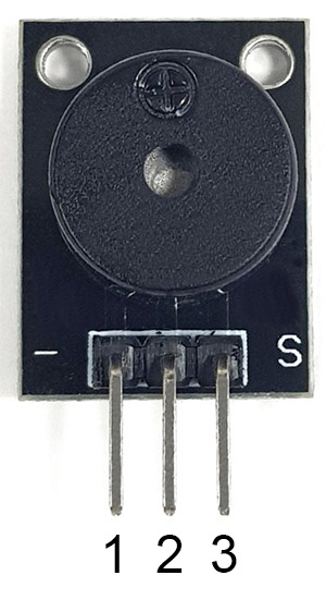
Pin Configuration
The KY-006 module has three pins, as described in the table below:
| Pin | Name | Description |
|---|---|---|
| 1 | VCC | Power supply pin (3.3V to 5V) |
| 2 | GND | Ground connection |
| 3 | OUT | Analog output pin that provides the sound signal |
Usage Instructions
The KY-006 sound sensor module is straightforward to use in a circuit. Follow the steps below to integrate it into your project:
Connecting the KY-006
- Power the Module: Connect the
VCCpin to a 3.3V or 5V power source and theGNDpin to the ground of your circuit. - Read the Output: Connect the
OUTpin to an analog input pin of your microcontroller (e.g., Arduino UNO) to read the sound signal.
Example Circuit with Arduino UNO
Below is an example of how to connect the KY-006 to an Arduino UNO:
| KY-006 Pin | Arduino UNO Pin |
|---|---|
| VCC | 5V |
| GND | GND |
| OUT | A0 |
Example Arduino Code
The following Arduino code reads the analog signal from the KY-006 and prints the sound level to the Serial Monitor:
// KY-006 Sound Sensor Example with Arduino UNO
// Connect KY-006 OUT pin to Arduino A0 pin
// Connect KY-006 VCC to Arduino 5V and GND to Arduino GND

const int soundSensorPin = A0; // KY-006 OUT pin connected to A0
int soundLevel = 0;            // Variable to store the sound level

void setup() {
  Serial.begin(9600); // Initialize Serial Monitor at 9600 baud rate
  pinMode(soundSensorPin, INPUT); // Set the sound sensor pin as input
}

void loop() {
  soundLevel = analogRead(soundSensorPin); // Read the analog value from KY-006
  Serial.print("Sound Level: ");           // Print label to Serial Monitor
  Serial.println(soundLevel);              // Print the sound level value
  delay(500);                              // Wait for 500ms before next reading
}
Important Considerations
- Power Supply: Ensure the module is powered within its operating voltage range (3.3V to 5V).
- Noise Sensitivity: The KY-006 detects general sound levels but does not differentiate between specific frequencies or types of sound.
- Placement: Place the module in an area where it can effectively detect sound without interference from vibrations or other noise sources.
Troubleshooting and FAQs
Common Issues and Solutions
No Output Signal
- Cause: Incorrect wiring or insufficient power supply.
- Solution: Double-check the connections and ensure the module is powered with 3.3V to 5V.
Inconsistent Readings
- Cause: Environmental noise or unstable power supply.
- Solution: Place the module in a stable environment and use a decoupling capacitor on the power supply if needed.
Low Sensitivity
- Cause: Module placement or sound source too far away.
- Solution: Move the module closer to the sound source or adjust its placement for better detection.
FAQs
Q: Can the KY-006 detect specific sounds like claps or voices?
A: No, the KY-006 is a general sound sensor and does not differentiate between specific sounds. It only detects changes in sound levels.
Q: Can I use the KY-006 with a 3.3V microcontroller?
A: Yes, the KY-006 operates within a voltage range of 3.3V to 5V, making it compatible with 3.3V microcontrollers like the ESP32.
Q: How can I increase the sensitivity of the KY-006?
A: The sensitivity of the KY-006 is fixed. However, you can improve detection by optimizing the module's placement and reducing environmental noise.
Q: Is the KY-006 suitable for outdoor use?
A: The KY-006 is not weatherproof. If used outdoors, it should be protected from moisture and extreme temperatures.
By following this documentation, you can effectively integrate the KY-006 sound sensor module into your projects and troubleshoot common issues.