How to Use Power Transformer: Examples, Pinouts, and Specs

 Design with Power Transformer in Cirkit Designer
Introduction
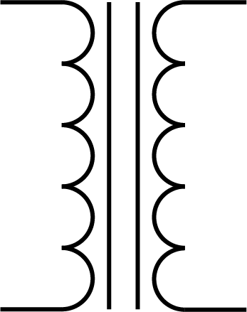
A power transformer is a passive electrical device that transfers electrical energy between two or more circuits through electromagnetic induction. It is a critical component in both power distribution and electronic applications, allowing for the adjustment of voltage levels to meet the needs of various devices and systems. Common applications include stepping down utility power to usable levels for homes and businesses, isolating circuits, and matching impedances in audio systems.
Explore Projects Built with Power Transformer

 Open Project in Cirkit Designer
 Open Project in Cirkit Designer
 Open Project in Cirkit Designer
 Open Project in Cirkit Designer
Explore Projects Built with Power Transformer

 Open Project in Cirkit Designer
 Open Project in Cirkit Designer
 Open Project in Cirkit Designer
 Open Project in Cirkit Designer
Technical Specifications
General Characteristics
- Type: Power Transformer
- Function: Voltage transformation and electrical isolation
- Cooling Method: Air/Natural, Oil-immersed (depending on the model)
- Frequency Range: Typically 50/60 Hz for power distribution, up to hundreds of kHz for switch-mode power supplies
Electrical Ratings
| Parameter | Description | Typical Values |
|---|---|---|
| Input Voltage (V) | Primary voltage rating | 110V, 220V, 400V, etc. |
| Output Voltage (V) | Secondary voltage rating | 5V, 12V, 24V, etc. |
| Power Rating (VA) | Apparent power capacity | 1VA to 1000MVA+ |
| Current Rating (A) | Maximum current for primary/secondary | Depends on power rating |
| Phase | Number of phases | Single-phase, Three-phase |
Pin Configuration and Descriptions
For a single-phase transformer:
| Pin Number | Description | Notes |
|---|---|---|
| P1, P2 | Primary winding pins | Connect to AC power source |
| S1, S2 | Secondary winding pins | Output pins for transformed voltage |
For a three-phase transformer, there would be additional pins for the phases and possibly for a neutral connection.
Usage Instructions
Integration into a Circuit
- Determine the Transformer Rating: Ensure the transformer's voltage and power ratings are suitable for your application.
- Wiring: Connect the primary winding to the power source and the secondary winding to the load. Observe proper polarity if required.
- Grounding: Properly ground the transformer to avoid electrical shocks and interference.
- Testing: Before full operation, test the transformer with a multimeter to ensure correct output voltage.
Best Practices
- Overload Protection: Use fuses or circuit breakers to protect against overcurrent conditions.
- Thermal Management: Ensure adequate ventilation around the transformer to prevent overheating.
- Regular Maintenance: Check for signs of wear, corrosion, and insulation breakdown.
Troubleshooting and FAQs
Common Issues
- No Output Voltage: Check for blown fuses, broken connections, or a damaged primary winding.
- Incorrect Output Voltage: Verify that the input voltage matches the transformer's specifications. Check for loose connections or shorted windings.
- Overheating: Ensure the transformer is not exceeding its power rating and that there is sufficient cooling.
FAQs
Q: Can I use a power transformer to step up voltage? A: Yes, transformers can step up or step down voltage depending on the design.
Q: How do I know if my transformer is three-phase or single-phase? A: Check the number of primary and secondary winding connections. Three-phase transformers will have three sets of windings.
Q: What does 'VA' rating mean? A: 'VA' stands for Volt-Ampere and is a measure of the apparent power the transformer can handle.
Example Code for Arduino UNO
If you are using a low-power transformer to power an Arduino UNO or its peripherals, you might need to convert AC from the transformer to DC. Here's an example of how to set up a simple rectifier circuit in code comments:
// No direct code is needed for the transformer itself, as it is a passive component.
// However, below is a pseudo-code outline for setting up a rectifier circuit to convert
// the transformer's AC output to a DC voltage suitable for an Arduino UNO.

// 1. Connect the secondary winding of the transformer to a rectifier circuit.
// 2. The rectifier converts AC to pulsating DC.
// 3. Use a filter capacitor to smooth the pulsating DC into a more stable DC voltage.
// 4. Connect a voltage regulator to get a consistent 5V output if necessary.
// 5. The regulated 5V can be used to power the Arduino UNO or its peripherals.
Remember, when working with power transformers and mains electricity, safety is paramount. Always consult a professional electrician or engineer if you are not experienced with high voltage and power systems.