
How to Use Adafruit APDS-9960: Examples, Pinouts, and Specs
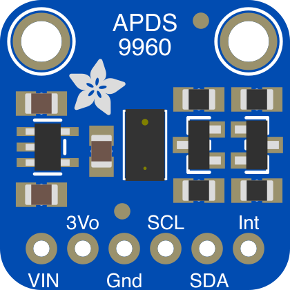
 Design with Adafruit APDS-9960 in Cirkit Designer
Introduction
The Adafruit APDS-9960 (Part ID: 3595) is a versatile sensor module that integrates multiple sensing capabilities into a compact design. It features ambient light sensing, proximity detection, RGB color sensing, and gesture recognition, making it ideal for a wide range of interactive projects and applications. This sensor is commonly used in touchless interfaces, robotics, smart lighting systems, and wearable devices.
With its I2C interface and small form factor, the APDS-9960 is easy to integrate into microcontroller-based systems, including Arduino and Raspberry Pi platforms.
Explore Projects Built with Adafruit APDS-9960
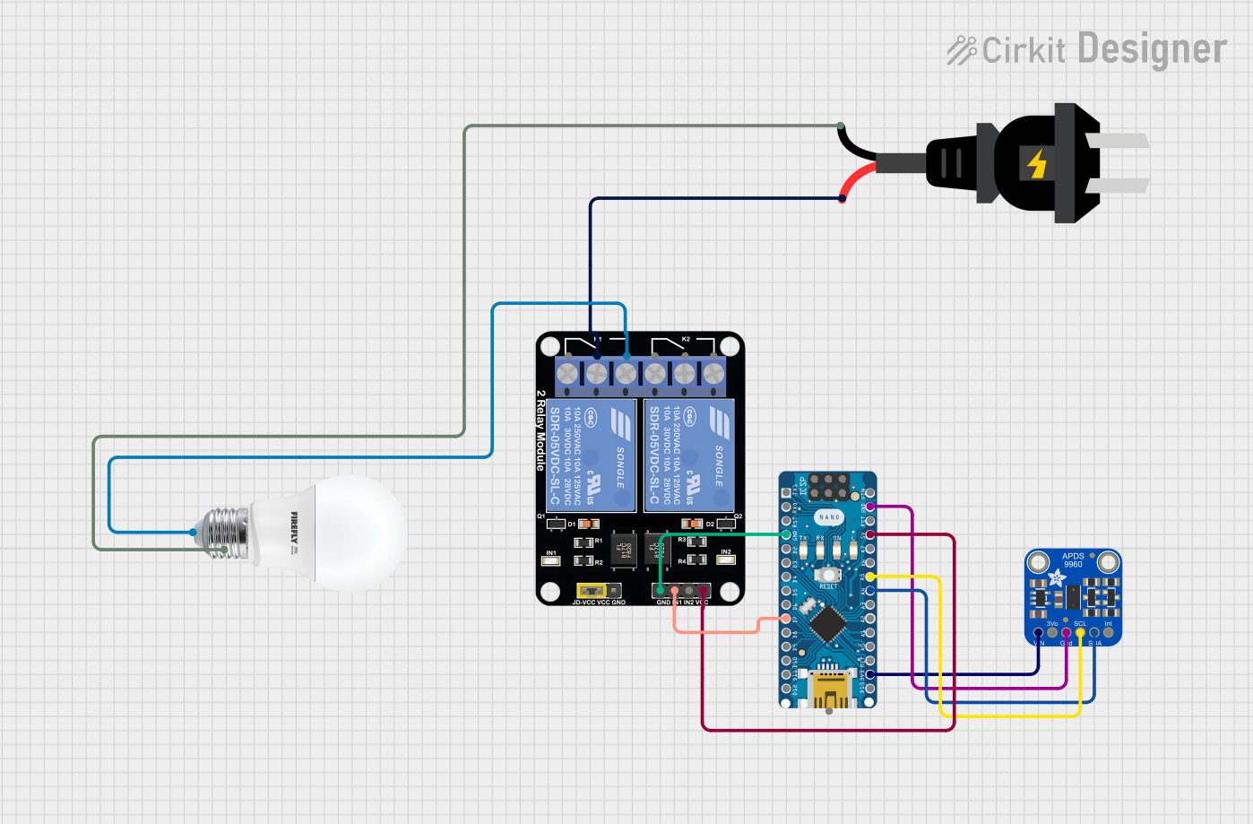 Open Project in Cirkit Designer
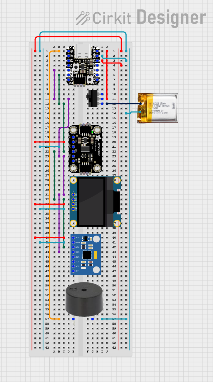 Open Project in Cirkit Designer
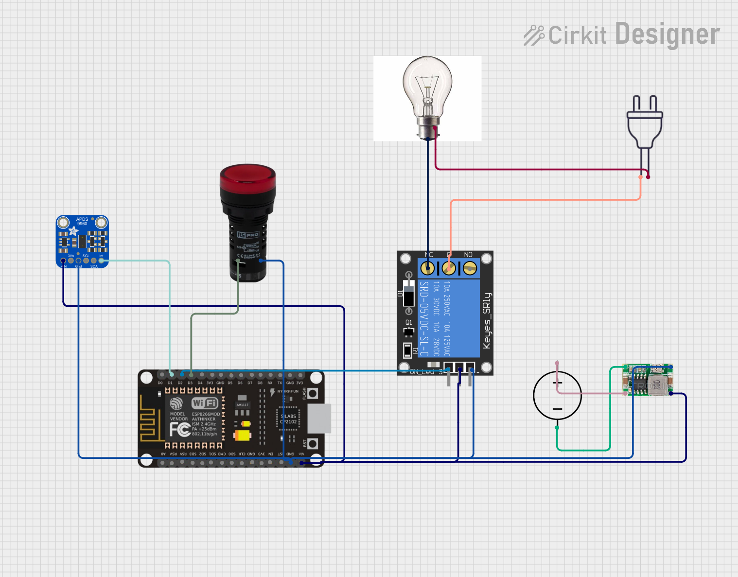 Open Project in Cirkit Designer
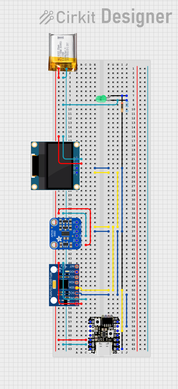 Open Project in Cirkit Designer
Explore Projects Built with Adafruit APDS-9960
Open Project in Cirkit DesignerOpen Project in Cirkit DesignerOpen Project in Cirkit DesignerOpen Project in Cirkit DesignerTechnical Specifications
Below are the key technical details and pin configuration for the Adafruit APDS-9960:
Key Technical Details
| Parameter | Value |
|---|---|
| Operating Voltage | 3.3V (logic level) |
| Supply Voltage Range | 2.4V to 3.6V |
| Interface | I2C |
| I2C Address | 0x39 (default) |
| Proximity Detection Range | Up to 10 cm |
| Gesture Detection Range | 10 cm to 20 cm |
| Ambient Light Sensitivity | 0.01 lux to 10,000 lux |
| RGB Color Resolution | 16-bit per channel |
| Operating Temperature | -40°C to +85°C |
| Dimensions | 20mm x 15mm x 2mm |
Pin Configuration
The Adafruit APDS-9960 module has the following pinout:
| Pin Name | Description |
|---|---|
| VIN | Power input (3.3V recommended) |
| GND | Ground |
| SDA | I2C data line |
| SCL | I2C clock line |
| INT | Interrupt output (active low) |
Usage Instructions
How to Use the APDS-9960 in a Circuit
- Power the Sensor: Connect the
VINpin to a 3.3V power source and theGNDpin to ground. - Connect I2C Lines: Connect the
SDAandSCLpins to the corresponding I2C pins on your microcontroller. For Arduino UNO, connectSDAto A4 andSCLto A5. - Interrupt Pin (Optional): If you want to use the interrupt feature, connect the
INTpin to a digital input pin on your microcontroller. - Install Required Libraries: Use the Adafruit APDS-9960 library, which simplifies communication with the sensor. Install it via the Arduino Library Manager.
- Write Code: Use the example code provided below to initialize and read data from the sensor.
Example Code for Arduino UNO
#include <Wire.h>
#include <Adafruit_APDS9960.h>

// Create an instance of the APDS-9960 sensor
Adafruit_APDS9960 apds;

// Setup function
void setup() {
  Serial.begin(9600); // Initialize serial communication
  while (!Serial) {
    delay(10); // Wait for Serial Monitor to open
  }

  // Initialize the sensor
  if (!apds.begin()) {
    Serial.println("Failed to initialize APDS-9960 sensor!");
    while (1); // Halt execution if initialization fails
  }
  Serial.println("APDS-9960 sensor initialized!");

  // Enable proximity and gesture detection
  apds.enableProximity(true);
  apds.enableGesture(true);
}

// Loop function
void loop() {
  // Check for gesture detection
  if (apds.gestureAvailable()) {
    int gesture = apds.readGesture();
    switch (gesture) {
      case APDS9960_UP:
        Serial.println("Gesture: UP");
        break;
      case APDS9960_DOWN:
        Serial.println("Gesture: DOWN");
        break;
      case APDS9960_LEFT:
        Serial.println("Gesture: LEFT");
        break;
      case APDS9960_RIGHT:
        Serial.println("Gesture: RIGHT");
        break;
      default:
        Serial.println("Gesture: UNKNOWN");
        break;
    }
  }

  // Read proximity data
  uint8_t proximity = apds.readProximity();
  Serial.print("Proximity: ");
  Serial.println(proximity);

  delay(100); // Small delay for stability
}
Important Considerations and Best Practices
- Power Supply: Ensure the sensor is powered with 3.3V. Using 5V may damage the module.
- I2C Pull-Up Resistors: The module includes pull-up resistors for the I2C lines. If you experience communication issues, verify that additional pull-ups are not causing conflicts.
- Interrupt Pin: The
INTpin is optional but can be used to reduce polling and improve efficiency in gesture detection applications. - Ambient Light Interference: Avoid placing the sensor in direct sunlight or near strong light sources, as this may affect its performance.
Troubleshooting and FAQs
Common Issues and Solutions
Sensor Not Detected on I2C Bus:
- Ensure the
SDAandSCLlines are correctly connected. - Verify that the I2C address (default: 0x39) matches the one in your code.
- Check for loose connections or damaged wires.
- Ensure the
Gesture Detection Not Working:
- Ensure the sensor is not obstructed and is within the recommended range (10-20 cm).
- Verify that gesture detection is enabled in the code (
apds.enableGesture(true)).
Proximity Readings Are Inaccurate:
- Ensure there are no reflective surfaces too close to the sensor.
- Calibrate the sensor if necessary by adjusting sensitivity settings in the library.
Ambient Light or Color Readings Are Incorrect:
- Avoid placing the sensor in environments with extreme lighting conditions.
- Ensure the sensor's optical window is clean and free of dust or smudges.
FAQs
Q: Can the APDS-9960 detect multiple gestures simultaneously?
A: No, the sensor detects one gesture at a time. It processes gestures sequentially.
Q: Can I use the APDS-9960 with a 5V microcontroller?
A: Yes, but you must use a logic level shifter to convert the 5V signals to 3.3V for the sensor.
Q: What is the maximum I2C clock speed supported by the APDS-9960?
A: The sensor supports I2C clock speeds up to 400 kHz (Fast Mode).
Q: How do I disable specific features like gesture detection?
A: Use the appropriate library functions (e.g., apds.enableGesture(false)) to disable features.
By following this documentation, you can effectively integrate and utilize the Adafruit APDS-9960 sensor in your projects.