How to Use L298 Dual H Bridge Motor Speed Controller: Examples, Pinouts, and Specs
Introduction
The L298 Dual H-Bridge Motor Speed Controller is a versatile motor driver IC designed to control the speed and direction of two DC motors or a single stepper motor. It is capable of handling high current loads, making it ideal for applications in robotics, automation, and other motor control projects. The L298 is widely used due to its robustness, ease of use, and compatibility with microcontrollers like Arduino.
Explore Projects Built with L298 Dual H Bridge Motor Speed Controller
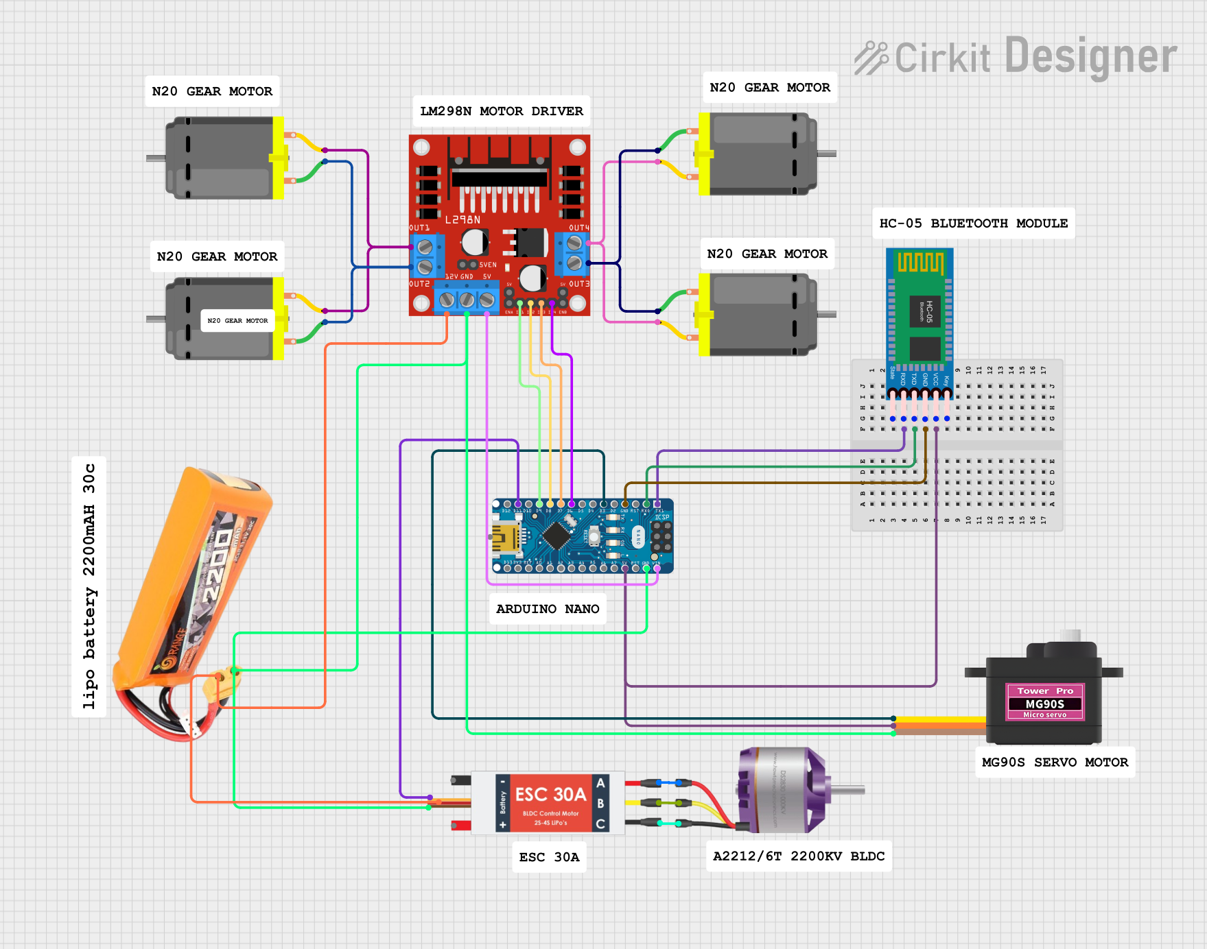
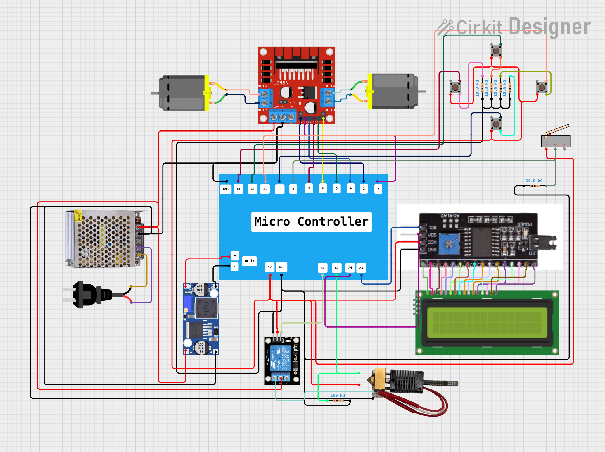

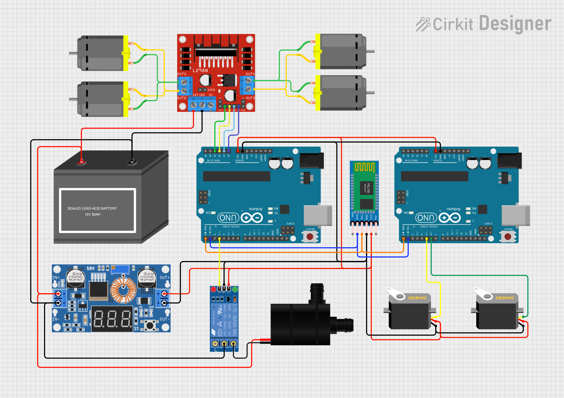
Explore Projects Built with L298 Dual H Bridge Motor Speed Controller
Common Applications
- Robotics: Driving wheels or robotic arms
- Automation: Conveyor belts, actuators, and industrial machinery
- DIY Projects: Remote-controlled cars, drones, and hobbyist robots
- Stepper Motor Control: For precise positioning in CNC machines or 3D printers
Technical Specifications
The L298 motor driver IC is designed to handle a wide range of motor control requirements. Below are its key technical details:
| Parameter | Value |
|---|---|
| Operating Voltage | 5V to 46V |
| Maximum Output Current | 2A per channel (4A total) |
| Logic Voltage | 5V |
| Power Dissipation | 25W (with proper heat sinking) |
| Control Inputs | TTL-compatible |
| Number of Channels | 2 (dual H-bridge) |
| Motor Types Supported | DC motors, stepper motors |
| Operating Temperature | -25°C to +130°C |
Pin Configuration and Descriptions
The L298 IC has 15 pins, each serving a specific purpose. Below is the pinout and description:
| Pin Number | Pin Name | Description |
|---|---|---|
| 1 | Enable A | Enables or disables motor A (active HIGH) |
| 2 | Input 1 | Logic input to control motor A direction |
| 3 | Input 2 | Logic input to control motor A direction |
| 4 | Output 1 | Motor A output terminal 1 |
| 5 | Output 2 | Motor A output terminal 2 |
| 6 | VSS | Logic voltage supply (5V) |
| 7 | Ground | Ground connection |
| 8 | VS | Motor power supply (up to 46V) |
| 9 | Output 3 | Motor B output terminal 1 |
| 10 | Output 4 | Motor B output terminal 2 |
| 11 | Input 3 | Logic input to control motor B direction |
| 12 | Input 4 | Logic input to control motor B direction |
| 13 | Enable B | Enables or disables motor B (active HIGH) |
| 14 | Ground | Ground connection |
| 15 | Sense A/B | Current sensing pins for motor A and B (optional, connect to ground if unused) |
Usage Instructions
How to Use the L298 in a Circuit
Power Connections:
- Connect the motor power supply (up to 46V) to the
VSpin. - Connect the logic voltage (5V) to the
VSSpin. - Connect the ground pins (
GND) to the common ground of the circuit.
- Connect the motor power supply (up to 46V) to the
Motor Connections:
- Connect the motor terminals to the
Outputpins (e.g.,Output 1andOutput 2for motor A). - Repeat for motor B if using two motors.
- Connect the motor terminals to the
Control Inputs:
- Use the
Inputpins to control the direction of the motors. For example:Input 1 = HIGHandInput 2 = LOWwill rotate motor A in one direction.Input 1 = LOWandInput 2 = HIGHwill rotate motor A in the opposite direction.
- Use the
Enablepins to turn the motors on or off. SetEnable AorEnable Bto HIGH to enable the respective motor.
- Use the
Optional Current Sensing:
- If current sensing is required, connect the
Sensepins to a resistor and measure the voltage drop.
- If current sensing is required, connect the
Important Considerations
- Heat Dissipation: The L298 can generate significant heat during operation. Use a heat sink or cooling fan to prevent overheating.
- Power Supply: Ensure the motor power supply voltage and current ratings match the motor's requirements.
- Logic Level Compatibility: The control inputs are TTL-compatible, making them suitable for direct connection to microcontrollers like Arduino.
Example: Controlling a DC Motor with Arduino UNO
Below is an example Arduino sketch to control the speed and direction of a DC motor using the L298:
// Define L298 pins connected to Arduino
const int enableA = 9;  // PWM pin to control motor speed
const int input1 = 8;   // Direction control pin 1
const int input2 = 7;   // Direction control pin 2

void setup() {
  // Set pin modes
  pinMode(enableA, OUTPUT);
  pinMode(input1, OUTPUT);
  pinMode(input2, OUTPUT);

  // Initialize motor to stop
  digitalWrite(input1, LOW);
  digitalWrite(input2, LOW);
  analogWrite(enableA, 0);  // Set speed to 0
}

void loop() {
  // Rotate motor in one direction at 50% speed
  digitalWrite(input1, HIGH);
  digitalWrite(input2, LOW);
  analogWrite(enableA, 128);  // 50% duty cycle (0-255)

  delay(2000);  // Run for 2 seconds

  // Rotate motor in the opposite direction at full speed
  digitalWrite(input1, LOW);
  digitalWrite(input2, HIGH);
  analogWrite(enableA, 255);  // 100% duty cycle

  delay(2000);  // Run for 2 seconds

  // Stop the motor
  digitalWrite(input1, LOW);
  digitalWrite(input2, LOW);
  analogWrite(enableA, 0);  // Set speed to 0

  delay(2000);  // Wait for 2 seconds
}
Troubleshooting and FAQs
Common Issues
Motor Not Running:
- Check the power supply connections to
VSandVSS. - Ensure the
Enablepin is set to HIGH. - Verify the motor connections to the
Outputpins.
- Check the power supply connections to
Overheating:
- Ensure a heat sink is attached to the L298 IC.
- Check that the motor's current draw does not exceed 2A per channel.
Erratic Motor Behavior:
- Verify the logic input signals are correct.
- Ensure the ground connections are properly shared between the L298 and the microcontroller.
FAQs
Q: Can the L298 drive stepper motors?
A: Yes, the L298 can drive a single stepper motor by using both H-bridge channels. You will need to sequence the inputs correctly to control the stepper motor.
Q: What is the maximum motor voltage the L298 can handle?
A: The L298 can handle motor supply voltages up to 46V.
Q: Do I need external diodes for the L298?
A: No, the L298 has built-in flyback diodes to protect against voltage spikes caused by inductive loads like motors.
Q: Can I use the L298 with a 3.3V microcontroller?
A: The L298 requires 5V logic levels for its control inputs. You may need a level shifter to interface with a 3.3V microcontroller.