How to Use Pulse Sensor: Examples, Pinouts, and Specs
Introduction
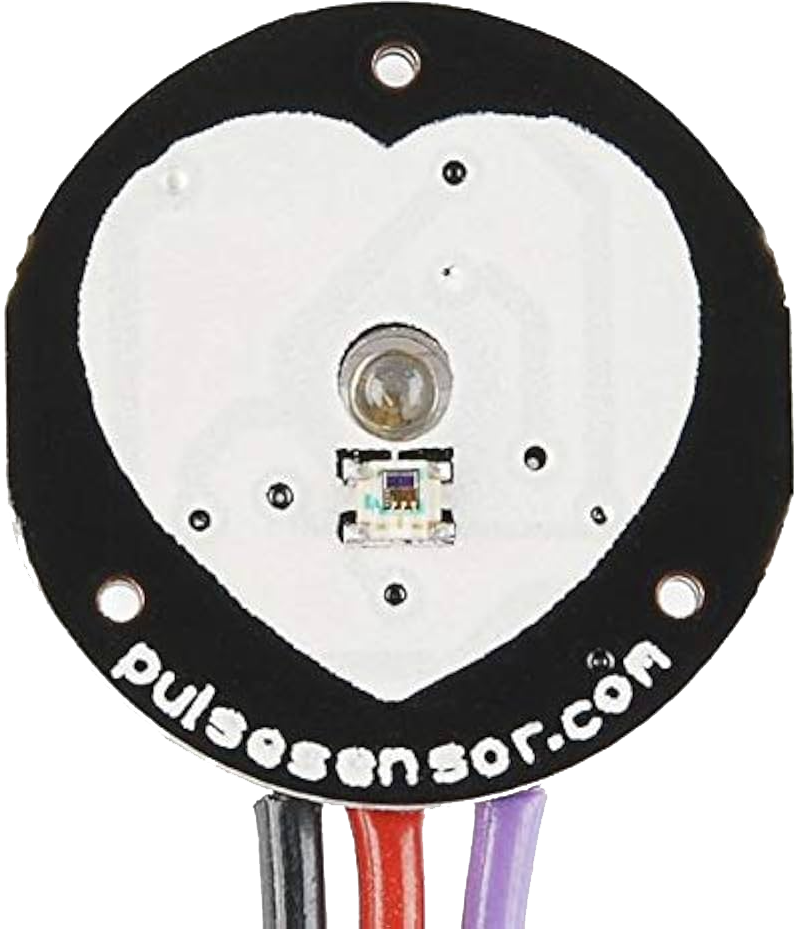
The Pulse Sensor is a compact and easy-to-use device designed to detect and measure the heartbeat of an individual. It operates using photoplethysmography (PPG), a technique that monitors changes in blood volume in the microvascular bed of tissue. This sensor is widely used in health monitoring systems, fitness trackers, and biofeedback applications. Its small size and compatibility with microcontrollers make it ideal for wearable devices and DIY electronics projects.
Explore Projects Built with Pulse Sensor
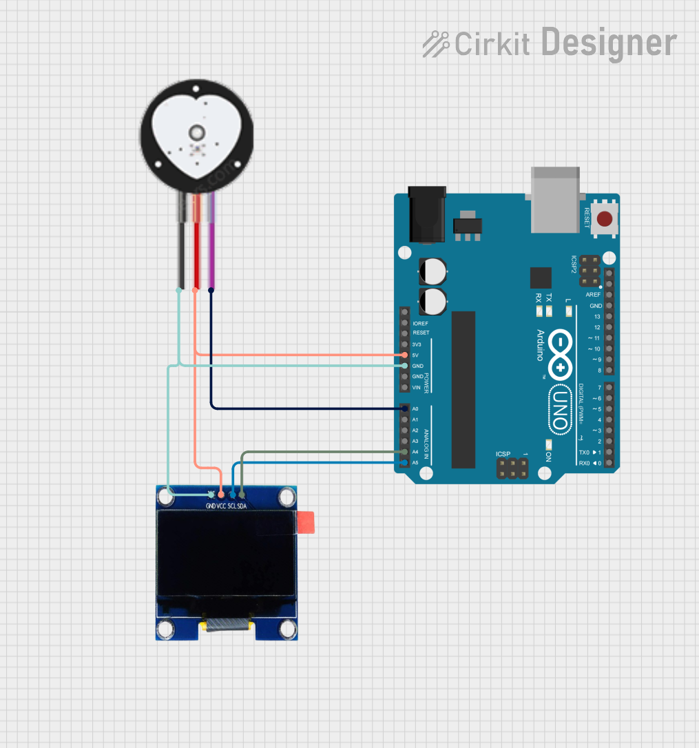
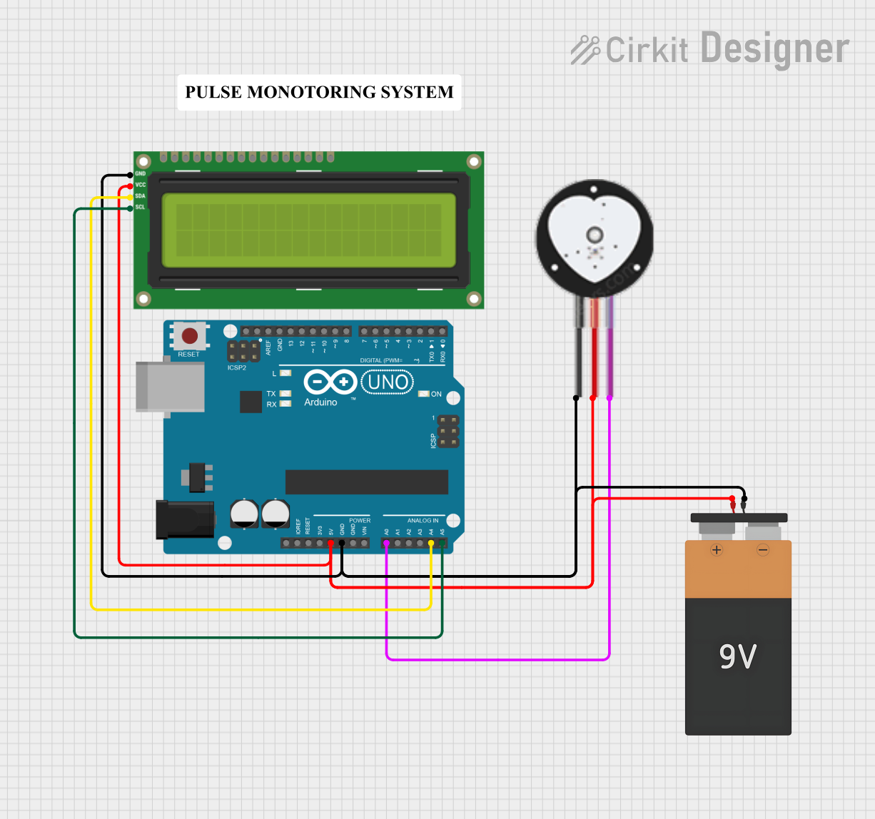
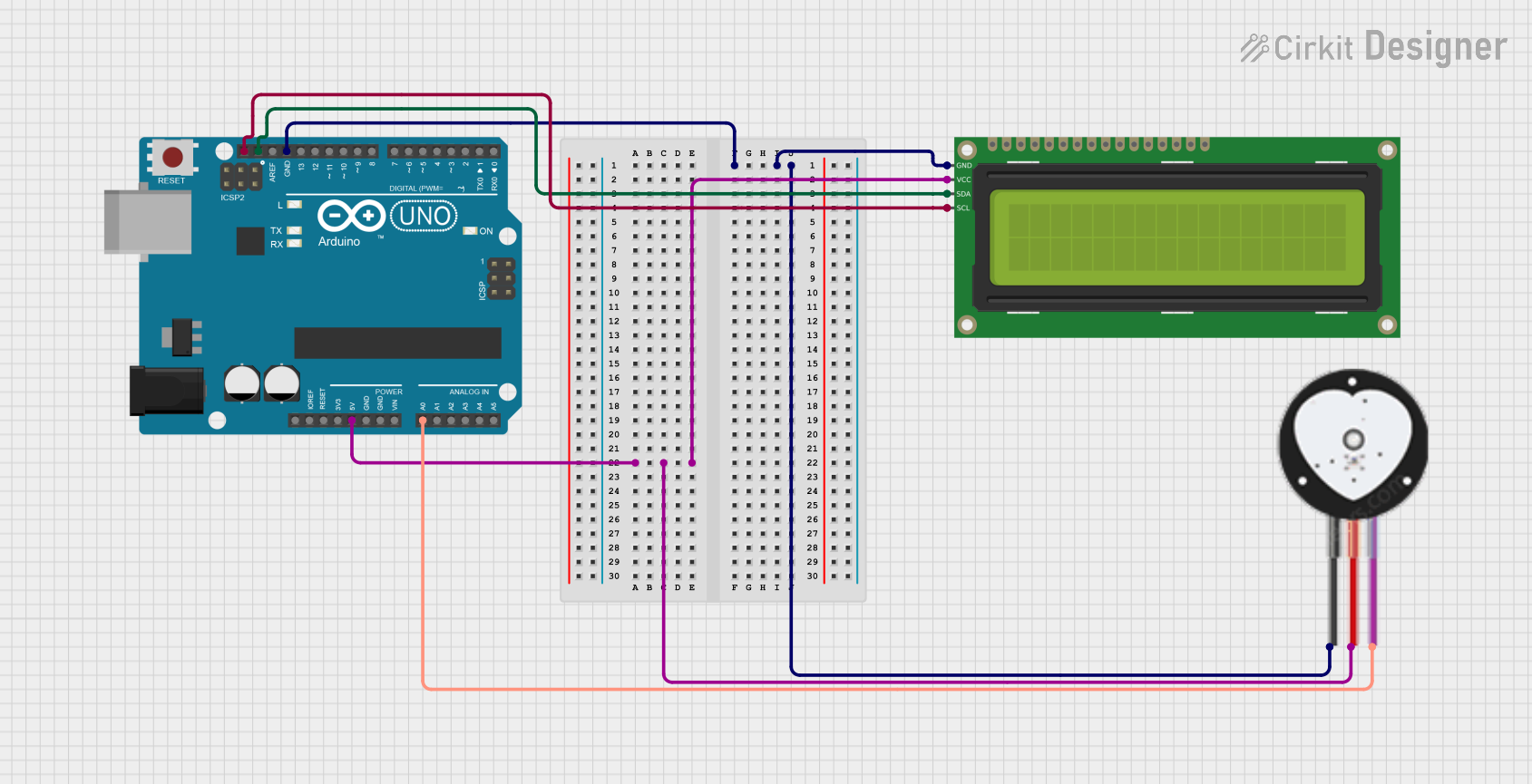
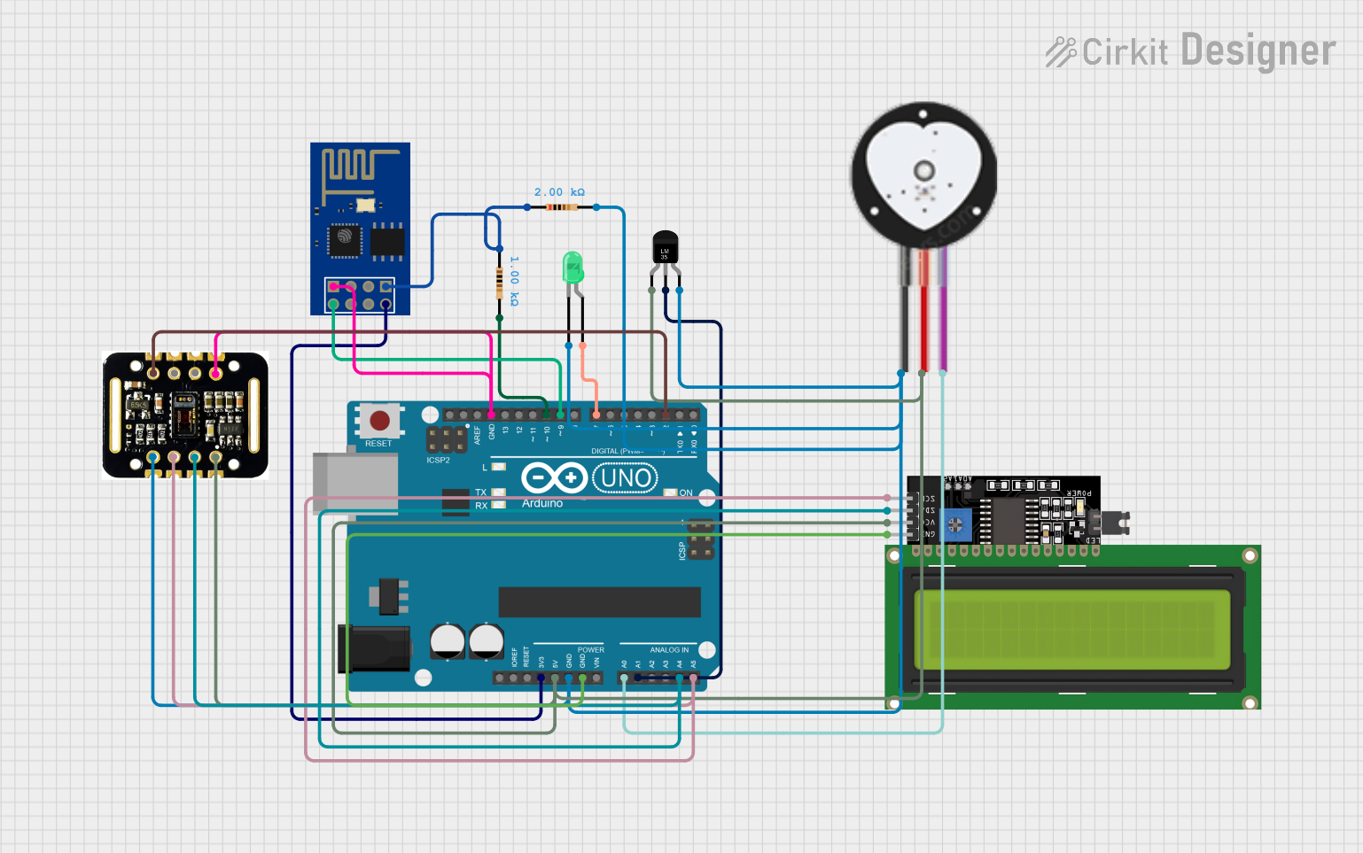
Explore Projects Built with Pulse Sensor
Common Applications and Use Cases
- Heart rate monitoring in fitness devices
- Health tracking systems
- Biofeedback and stress management tools
- DIY electronics and Arduino-based projects
- Educational tools for learning about biosignals
Technical Specifications
The Pulse Sensor is designed for simplicity and ease of integration into various projects. Below are its key technical details:
| Parameter | Specification |
|---|---|
| Operating Voltage | 3.3V to 5V |
| Current Consumption | ~4mA |
| Output Signal | Analog (0-1023 for 10-bit ADC) |
| Sensor Type | Photoplethysmography (PPG) |
| Dimensions | ~16mm diameter |
| Cable Length | ~24 inches |
Pin Configuration and Descriptions
The Pulse Sensor typically comes with a 3-pin connector. Below is the pinout:
| Pin | Name | Description |
|---|---|---|
| 1 | VCC | Power supply pin (3.3V or 5V) |
| 2 | GND | Ground connection |
| 3 | Signal | Analog output signal representing heartbeat data |
Usage Instructions
How to Use the Pulse Sensor in a Circuit
Connect the Pins:
- Connect the
VCCpin to the 3.3V or 5V power supply of your microcontroller. - Connect the
GNDpin to the ground of your circuit. - Connect the
Signalpin to an analog input pin on your microcontroller (e.g., A0 on an Arduino UNO).
- Connect the
Place the Sensor:
- Attach the sensor to a fingertip or earlobe using the included Velcro strap or clip.
- Ensure the sensor is securely in place to avoid motion artifacts.
Read the Signal:
- Use the analog input of your microcontroller to read the signal from the
Signalpin. - Process the signal to extract heartbeat data.
- Use the analog input of your microcontroller to read the signal from the
Important Considerations and Best Practices
- Avoid Motion Artifacts: Minimize movement while using the sensor to ensure accurate readings.
- Ambient Light: Use the sensor in a low-light environment or shield it from ambient light to reduce interference.
- Power Supply: Ensure a stable power supply to avoid noise in the output signal.
- Signal Processing: Use a low-pass filter or software-based algorithms to smooth the raw signal and detect heartbeats accurately.
Example Code for Arduino UNO
Below is an example of how to use the Pulse Sensor with an Arduino UNO:
// Example code for using the Pulse Sensor with Arduino UNO
// Connect the Signal pin to A0, VCC to 5V, and GND to GND

const int pulsePin = A0;  // Analog pin connected to the Signal pin
int pulseValue = 0;       // Variable to store the analog reading

void setup() {
  Serial.begin(9600);  // Initialize serial communication
  pinMode(pulsePin, INPUT);  // Set the pulse pin as input
}

void loop() {
  pulseValue = analogRead(pulsePin);  // Read the analog value from the sensor
  Serial.println(pulseValue);  // Print the value to the Serial Monitor

  // Add a small delay to stabilize readings
  delay(10);
}
Notes:
- Use the Serial Monitor in the Arduino IDE to observe the raw signal values.
- For advanced applications, consider using libraries like the PulseSensor Playground library for signal processing and heartbeat detection.
Troubleshooting and FAQs
Common Issues and Solutions
No Signal Detected:
- Ensure the sensor is properly connected to the microcontroller.
- Verify that the sensor is securely placed on the skin.
Inconsistent Readings:
- Minimize movement and ensure the sensor is not exposed to excessive ambient light.
- Check for loose connections in the circuit.
High Noise in Output:
- Use a low-pass filter to smooth the signal.
- Ensure the power supply is stable and free from noise.
Sensor Overheating:
- Verify that the operating voltage does not exceed 5V.
- Avoid prolonged use without breaks.
FAQs
Q: Can the Pulse Sensor be used with a 3.3V microcontroller?
A: Yes, the sensor is compatible with both 3.3V and 5V systems.
Q: How do I process the raw signal to calculate heart rate?
A: You can use the PulseSensor Playground library or implement a peak detection algorithm to calculate beats per minute (BPM).
Q: Can the sensor be used on other body parts?
A: Yes, the sensor can be used on the fingertip, earlobe, or other areas with good blood flow.
Q: Is the Pulse Sensor waterproof?
A: No, the sensor is not waterproof and should be kept dry during use.
By following this documentation, you can effectively integrate the Pulse Sensor into your projects and achieve accurate heart rate monitoring.