Cirkit Designer Logo
Cirkit Designer
Your all-in-one circuit design IDE
Home / 
Component Documentation

How to Use Adafruit HT16K33 Breakout 16x8 LED Matrix Driver: Examples, Pinouts, and Specs

Image of Adafruit HT16K33 Breakout 16x8 LED Matrix Driver
Cirkit Designer LogoDesign with Adafruit HT16K33 Breakout 16x8 LED Matrix Driver in Cirkit Designer

Introduction

The Adafruit HT16K33 Breakout is a versatile LED matrix driver module designed to control a 16x8 matrix, totaling 128 LEDs. It utilizes the HT16K33 chip to manage individual LED states, offering an I2C interface for communication with microcontrollers such as Arduino, Raspberry Pi, and others. This breakout is ideal for creating digital signage, gaming displays, or any project requiring a bright, customizable LED array.

Explore Projects Built with Adafruit HT16K33 Breakout 16x8 LED Matrix Driver

Use Cirkit Designer to design, explore, and prototype these projects online. Some projects support real-time simulation. Click "Open Project" to start designing instantly!
ESP32-Controlled WS2812 LED Matrix Display with Resistor
Image of esp32 door sign project: A project utilizing Adafruit HT16K33 Breakout 16x8 LED Matrix Driver in a practical application
This circuit features an ESP32 microcontroller connected to a 32x8 WS2812 LED matrix. The ESP32 controls the LED matrix through a 220-ohm resistor connected to its D12 pin, providing data input to the matrix, while power and ground connections are shared between the ESP32 and the LED matrix.
Cirkit Designer LogoOpen Project in Cirkit Designer
ESP8266 NodeMCU Controlled 8x8 LED Matrix Display
Image of Nodemcu: A project utilizing Adafruit HT16K33 Breakout 16x8 LED Matrix Driver in a practical application
This circuit connects an ESP8266 NodeMCU microcontroller to an 8x8 LED matrix display. The NodeMCU controls the matrix using digital pins D5, D7, and D8 for chip select (CS), data input (DIN), and clock (CLK) signals, respectively. The circuit is designed to display patterns or characters on the LED matrix, which are driven by the microcontroller.
Cirkit Designer LogoOpen Project in Cirkit Designer
ESP32-Controlled Dual 8x8 LED Matrix Display with NTP Time Synchronization
Image of time: A project utilizing Adafruit HT16K33 Breakout 16x8 LED Matrix Driver in a practical application
This circuit features an ESP32 microcontroller connected to two cascaded 8x8 LED matrix displays, powered by a 3.3V battery. The ESP32 drives the displays to show time and other information, with the code indicating functionality for connecting to WiFi, synchronizing time via NTP, and displaying data on the matrices using custom fonts. Additionally, there is a separate 3.3V battery powering a red LED, which appears to function as a simple indicator light.
Cirkit Designer LogoOpen Project in Cirkit Designer
Arduino UNO Controlled LED Matrix and LCD Interface with Joystick Interaction
Image of Digital Game Circuit: A project utilizing Adafruit HT16K33 Breakout 16x8 LED Matrix Driver in a practical application
This circuit features an Arduino UNO microcontroller interfaced with an 8x8 LED matrix, an LCD screen, and a KY-023 Dual Axis Joystick Module. The Arduino controls the LED matrix via digital pins D10-D12 and powers the matrix, LCD, and joystick module from its 5V output. The joystick's analog outputs are connected to the Arduino's analog inputs A0 and A1 for position sensing, while the LCD is controlled through digital pins D2-D6 and D13 for display purposes.
Cirkit Designer LogoOpen Project in Cirkit Designer

Explore Projects Built with Adafruit HT16K33 Breakout 16x8 LED Matrix Driver

Use Cirkit Designer to design, explore, and prototype these projects online. Some projects support real-time simulation. Click "Open Project" to start designing instantly!
Image of esp32 door sign project: A project utilizing Adafruit HT16K33 Breakout 16x8 LED Matrix Driver in a practical application
ESP32-Controlled WS2812 LED Matrix Display with Resistor
This circuit features an ESP32 microcontroller connected to a 32x8 WS2812 LED matrix. The ESP32 controls the LED matrix through a 220-ohm resistor connected to its D12 pin, providing data input to the matrix, while power and ground connections are shared between the ESP32 and the LED matrix.
Cirkit Designer LogoOpen Project in Cirkit Designer
Image of Nodemcu: A project utilizing Adafruit HT16K33 Breakout 16x8 LED Matrix Driver in a practical application
ESP8266 NodeMCU Controlled 8x8 LED Matrix Display
This circuit connects an ESP8266 NodeMCU microcontroller to an 8x8 LED matrix display. The NodeMCU controls the matrix using digital pins D5, D7, and D8 for chip select (CS), data input (DIN), and clock (CLK) signals, respectively. The circuit is designed to display patterns or characters on the LED matrix, which are driven by the microcontroller.
Cirkit Designer LogoOpen Project in Cirkit Designer
Image of time: A project utilizing Adafruit HT16K33 Breakout 16x8 LED Matrix Driver in a practical application
ESP32-Controlled Dual 8x8 LED Matrix Display with NTP Time Synchronization
This circuit features an ESP32 microcontroller connected to two cascaded 8x8 LED matrix displays, powered by a 3.3V battery. The ESP32 drives the displays to show time and other information, with the code indicating functionality for connecting to WiFi, synchronizing time via NTP, and displaying data on the matrices using custom fonts. Additionally, there is a separate 3.3V battery powering a red LED, which appears to function as a simple indicator light.
Cirkit Designer LogoOpen Project in Cirkit Designer
Image of Digital Game Circuit: A project utilizing Adafruit HT16K33 Breakout 16x8 LED Matrix Driver in a practical application
Arduino UNO Controlled LED Matrix and LCD Interface with Joystick Interaction
This circuit features an Arduino UNO microcontroller interfaced with an 8x8 LED matrix, an LCD screen, and a KY-023 Dual Axis Joystick Module. The Arduino controls the LED matrix via digital pins D10-D12 and powers the matrix, LCD, and joystick module from its 5V output. The joystick's analog outputs are connected to the Arduino's analog inputs A0 and A1 for position sensing, while the LCD is controlled through digital pins D2-D6 and D13 for display purposes.
Cirkit Designer LogoOpen Project in Cirkit Designer

Common Applications and Use Cases

  • Digital clocks and timers
  • Scrolling text displays
  • Simple graphics and animations
  • Gaming displays and scoreboards
  • Interactive art installations

Technical Specifications

Key Technical Details

  • Supply Voltage (Vcc): 4.5V to 5.5V
  • Logic Level Voltage: 3.3V (5V tolerant)
  • Max Current (per LED): 20mA
  • Max Current (total): 400mA (when all LEDs are on)
  • Communication Interface: I2C
  • I2C Address Range: 0x70 to 0x77 (selectable with solder jumpers)
  • Operating Temperature: -40°C to +85°C

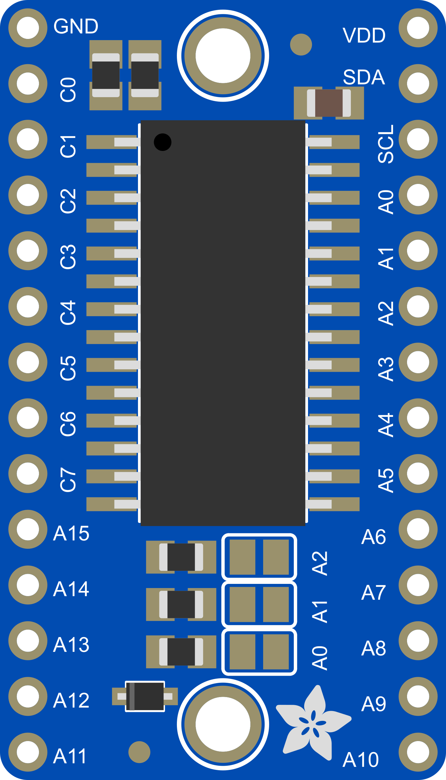
Pin Configuration and Descriptions

Pin Number Name Description
1 GND Ground connection
2 VCC Power supply (4.5V to 5.5V)
3 SDA I2C data line
4 SCL I2C clock line
5-12 ADDR Address selection pins (A0-A6)

Usage Instructions

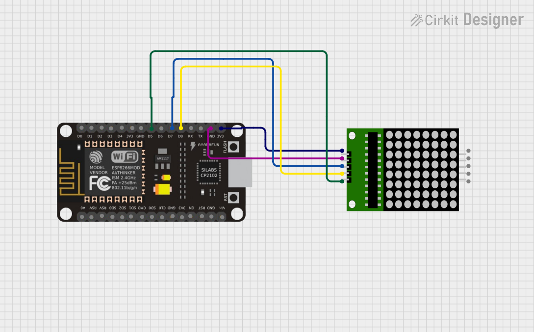
Integrating with a Circuit

  1. Power Connections: Connect the VCC pin to a 4.5V to 5.5V power supply and the GND pin to the ground.
  2. I2C Connections: Connect the SDA and SCL pins to the corresponding I2C data and clock lines on your microcontroller.
  3. Address Selection: Set the I2C address using the ADDR pins by soldering the appropriate jumpers.

Important Considerations and Best Practices

  • Ensure that the power supply is within the specified voltage range to prevent damage.
  • Use pull-up resistors on the I2C lines if they are not provided by the microcontroller.
  • Avoid driving all LEDs at maximum brightness simultaneously to prevent exceeding the maximum current rating.
  • To reduce power consumption and heat, manage brightness levels efficiently.

Example Code for Arduino UNO

#include <Wire.h>
#include "Adafruit_LEDBackpack.h"

Adafruit_8x16matrix matrix = Adafruit_8x16matrix();

void setup() {
  matrix.begin(0x70); // Initialize the matrix with the I2C address
  matrix.setBrightness(10); // Set brightness level (0 is dim, 15 is bright)
}

void loop() {
  matrix.clear(); // Clear the matrix display
  matrix.setCursor(0, 0); // Set cursor at top-left corner
  matrix.print("Hello"); // Print "Hello" on the matrix
  matrix.writeDisplay(); // Update the display with the new data
  delay(2000); // Wait for 2 seconds
}

Ensure that the Adafruit LED Backpack library is installed in your Arduino IDE before uploading this code to your Arduino UNO.

Troubleshooting and FAQs

Common Issues

  • LEDs Not Lighting Up: Check the power supply connections and ensure the I2C lines are properly connected.
  • Dim Display: Increase the brightness using setBrightness() or check the power supply voltage.
  • Incorrect Characters Displayed: Verify that the correct I2C address is used in the begin() function.

Solutions and Tips for Troubleshooting

  • Double-check wiring, especially the I2C connections.
  • Use the i2cdetect tool or similar to confirm the device's I2C address.
  • Ensure that there are no solder bridges on the ADDR pins that might cause an incorrect address setting.
  • If using multiple HT16K33 devices on the same I2C bus, ensure each has a unique address.

FAQs

Q: Can I chain multiple HT16K33 breakouts together? A: Yes, you can connect multiple devices on the same I2C bus with different addresses.

Q: How do I change the I2C address of the breakout? A: Solder the appropriate combination of ADDR jumpers to set the desired address.

Q: What is the maximum number of LEDs that can be controlled with one HT16K33 breakout? A: The breakout can control up to 128 LEDs arranged in a 16x8 matrix.

Q: Can the HT16K33 breakout be used with a 3.3V system? A: Yes, the logic level is 3.3V tolerant, but ensure that VCC is within the specified range.

For further assistance, consult the Adafruit HT16K33 Breakout forums or contact technical support.