How to Use NodeMCU: Examples, Pinouts, and Specs
Introduction
NodeMCU is an open-source IoT platform based on the ESP8266 Wi-Fi module. It features a built-in microcontroller and supports the Lua script interpreter, making it an excellent choice for developing connected devices. With its compact design and integrated Wi-Fi capabilities, NodeMCU simplifies the process of creating IoT applications by combining hardware and software in a single platform.
Explore Projects Built with NodeMCU

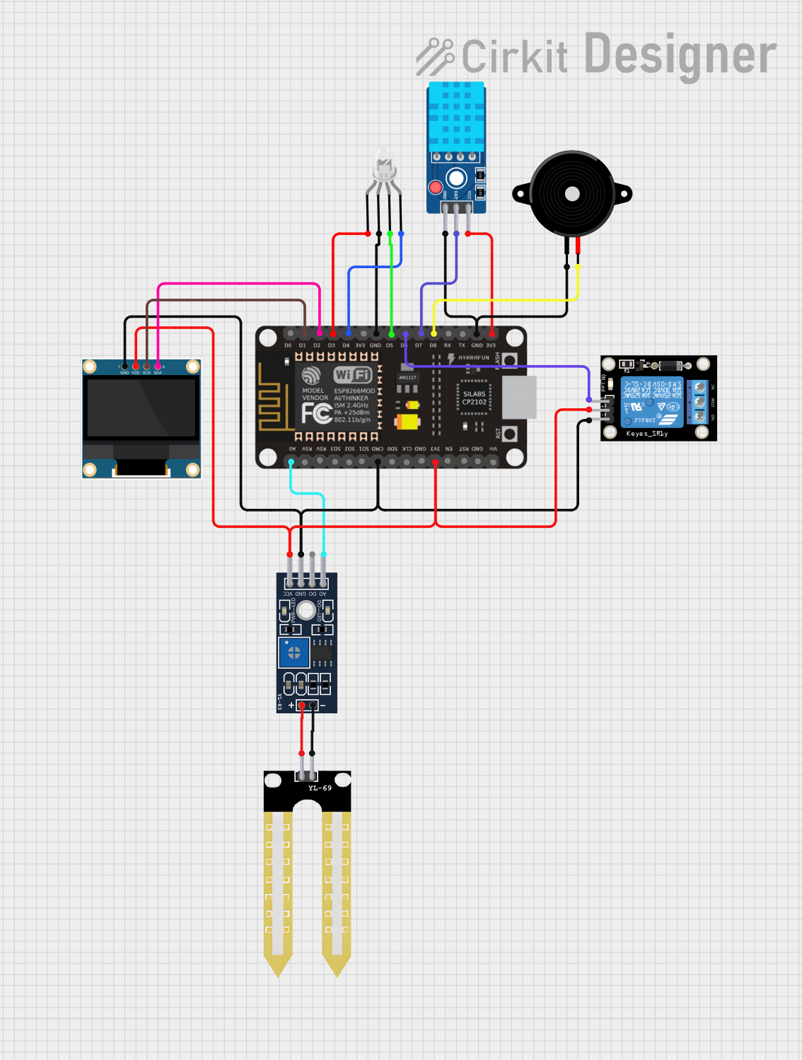
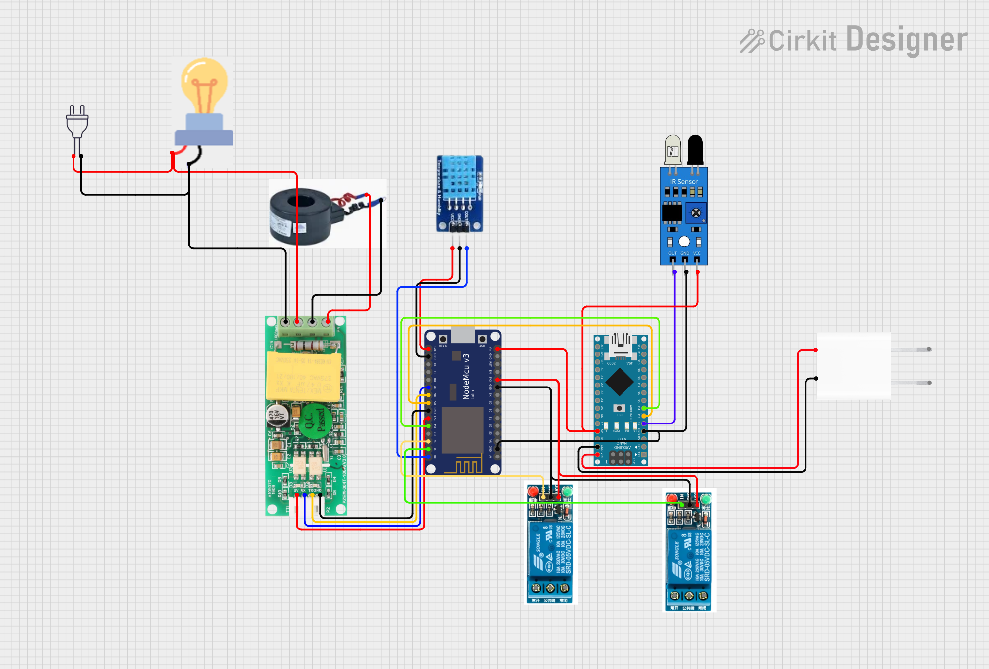
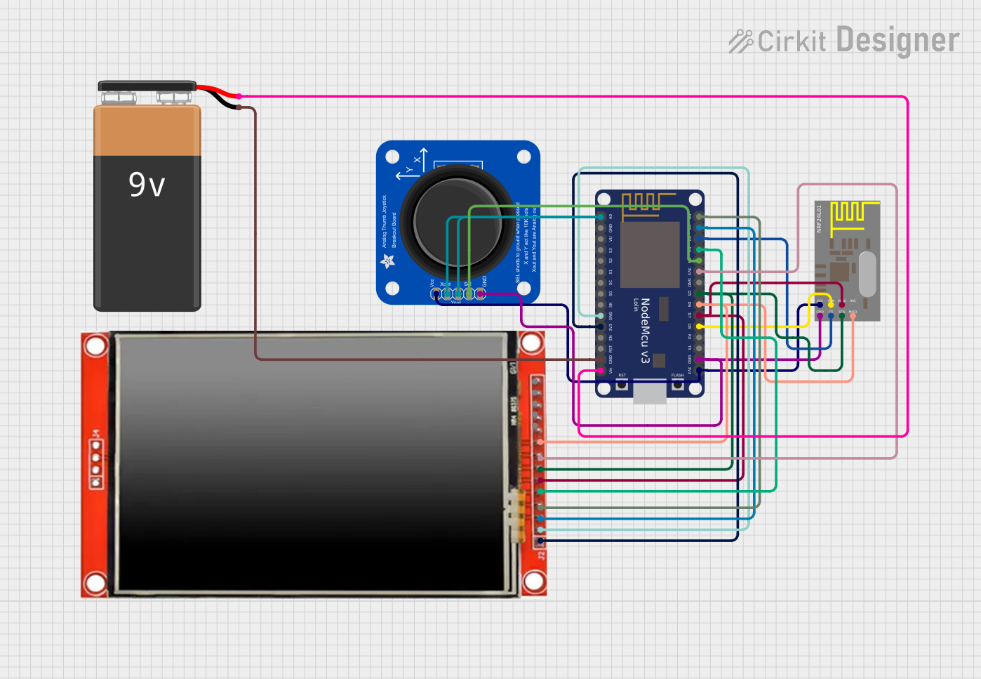
Explore Projects Built with NodeMCU
Common Applications and Use Cases
- Home automation systems
- Smart appliances
- IoT data logging and monitoring
- Wireless sensor networks
- Prototyping connected devices
- Remote control systems
Technical Specifications
Key Technical Details
- Microcontroller: ESP8266 (Tensilica L106 32-bit RISC processor)
- Clock Speed: 80 MHz (can be overclocked to 160 MHz)
- Flash Memory: 4 MB (varies by model)
- RAM: 64 KB instruction RAM, 96 KB data RAM
- Wi-Fi: IEEE 802.11 b/g/n, integrated TCP/IP stack
- Operating Voltage: 3.3V
- Input Voltage: 4.5V–10V (via VIN pin)
- Digital I/O Pins: 11 (GPIO0–GPIO16, excluding GPIO6–GPIO11)
- Analog Input: 1 (10-bit ADC, 0–3.3V range)
- Communication Protocols: UART, SPI, I2C, PWM
- Power Consumption: ~80 mA (active), ~10 µA (deep sleep)
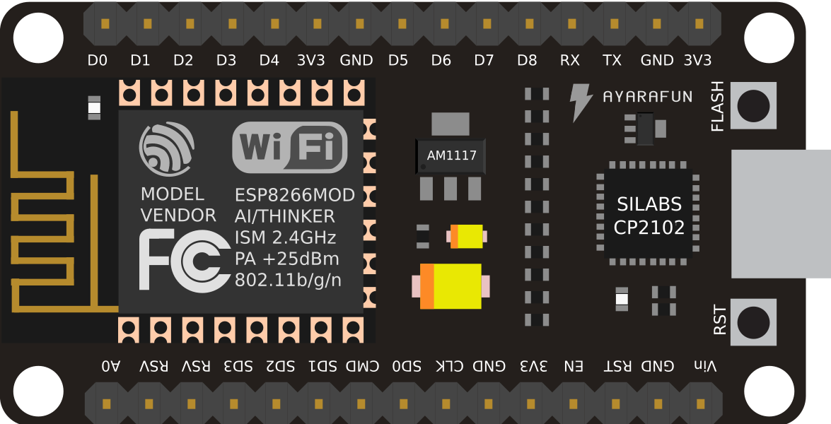
Pin Configuration and Descriptions
| Pin | Name | Description |
|---|---|---|
| 1 | VIN | Input voltage (4.5V–10V) for powering the board. |
| 2 | GND | Ground connection. |
| 3 | 3V3 | Regulated 3.3V output. |
| 4 | D0 (GPIO16) | General-purpose digital I/O pin. |
| 5 | D1 (GPIO5) | General-purpose digital I/O pin, often used for I2C (SCL). |
| 6 | D2 (GPIO4) | General-purpose digital I/O pin, often used for I2C (SDA). |
| 7 | D3 (GPIO0) | General-purpose digital I/O pin, also used for boot mode selection. |
| 8 | D4 (GPIO2) | General-purpose digital I/O pin, connected to the onboard LED. |
| 9 | D5 (GPIO14) | General-purpose digital I/O pin, often used for SPI (SCLK). |
| 10 | D6 (GPIO12) | General-purpose digital I/O pin, often used for SPI (MISO). |
| 11 | D7 (GPIO13) | General-purpose digital I/O pin, often used for SPI (MOSI). |
| 12 | D8 (GPIO15) | General-purpose digital I/O pin, often used for SPI (CS). |
| 13 | A0 | Analog input pin (0–3.3V). |
| 14 | RST | Reset pin. Pull low to reset the board. |
Usage Instructions
How to Use the NodeMCU in a Circuit
- Powering the NodeMCU:
- Use the VIN pin to supply 4.5V–10V, or connect a 5V USB cable to the micro-USB port.
- Ensure the power source can provide at least 500 mA for stable operation.
- Connecting Peripherals:
- Use the GPIO pins for digital input/output, PWM, or communication protocols like I2C and SPI.
- Connect sensors or actuators to the appropriate pins, ensuring voltage levels are within the 3.3V range.
- Programming the NodeMCU:
- Install the Arduino IDE or NodeMCU firmware (Lua interpreter).
- Select the correct board (e.g., "NodeMCU 1.0 (ESP-12E Module)") in the Arduino IDE.
- Connect the NodeMCU to your computer via USB and upload your code.
Important Considerations and Best Practices
- Voltage Levels: The GPIO pins operate at 3.3V. Avoid applying 5V directly to the pins to prevent damage.
- Deep Sleep Mode: Use deep sleep mode to reduce power consumption in battery-powered applications.
- Pull-Up/Down Resistors: Some GPIO pins require external pull-up or pull-down resistors for stable operation.
- Boot Mode: Ensure GPIO0 is pulled high during normal operation to avoid entering bootloader mode.
Example Code for Arduino IDE
The following example demonstrates how to blink the onboard LED (connected to GPIO2):
// Define the onboard LED pin
const int ledPin = 2; // GPIO2 is connected to the onboard LED

void setup() {
  pinMode(ledPin, OUTPUT); // Set the LED pin as an output
}

void loop() {
  digitalWrite(ledPin, HIGH); // Turn the LED on
  delay(1000);                // Wait for 1 second
  digitalWrite(ledPin, LOW);  // Turn the LED off
  delay(1000);                // Wait for 1 second
}
Troubleshooting and FAQs
Common Issues and Solutions
- NodeMCU Not Detected by Computer:
- Ensure the USB cable is functional and supports data transfer.
- Install the correct USB-to-serial driver (e.g., CH340 or CP2102) for your NodeMCU model.
- Upload Errors in Arduino IDE:
- Check the selected board and port in the Arduino IDE settings.
- Press and hold the "Flash" button on the NodeMCU while uploading the code.
- Wi-Fi Connection Fails:
- Verify the SSID and password in your code.
- Ensure the Wi-Fi network is within range and supports 2.4 GHz (NodeMCU does not support 5 GHz).
- GPIO Pin Malfunction:
- Check for conflicting pin assignments in your code.
- Ensure the connected peripherals are within the 3.3V operating range.
FAQs
Q: Can I power the NodeMCU with a 5V power supply?
A: Yes, you can power the NodeMCU via the VIN pin or micro-USB port with a 5V supply.Q: How do I reset the NodeMCU?
A: Press the "RST" button on the board or pull the RST pin low.Q: Can I use the NodeMCU with 5V sensors?
A: Use a voltage divider or level shifter to step down the 5V signal to 3.3V for compatibility.Q: What is the maximum Wi-Fi range of the NodeMCU?
A: The range depends on environmental factors but is typically around 30–50 meters indoors.