
How to Use KidBright32 V1.3: Examples, Pinouts, and Specs
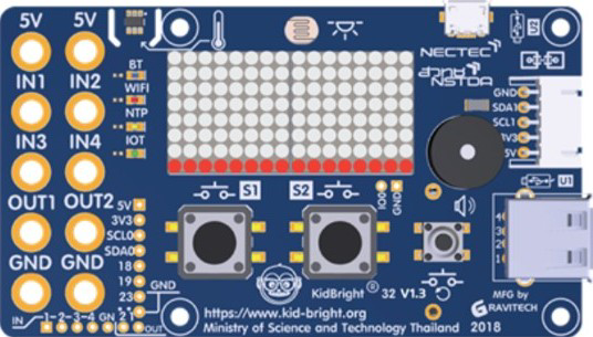
 Design with KidBright32 V1.3 in Cirkit Designer
Introduction
The KidBright32 V1.3, manufactured by Gravitech, is a versatile microcontroller board designed specifically for educational purposes. It is equipped with a variety of input/output options, built-in sensors, and compatibility with multiple programming environments. This makes it an excellent tool for learning electronics, programming, and IoT development. The board is based on the ESP32 microcontroller, offering robust performance and wireless connectivity.
Explore Projects Built with KidBright32 V1.3
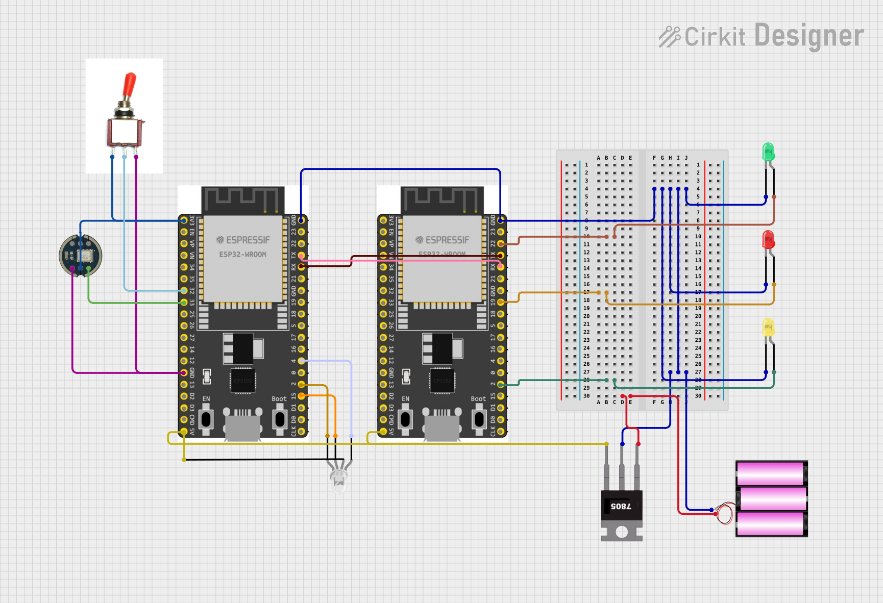 Open Project in Cirkit Designer
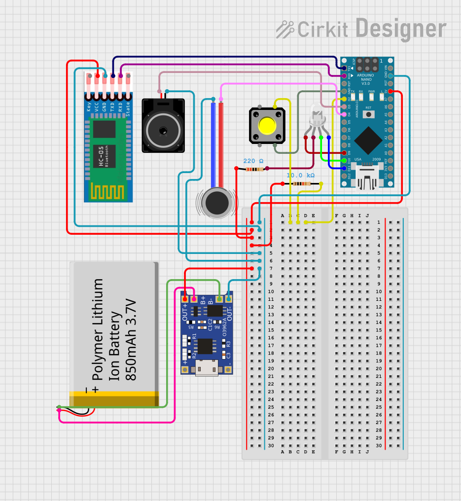 Open Project in Cirkit Designer
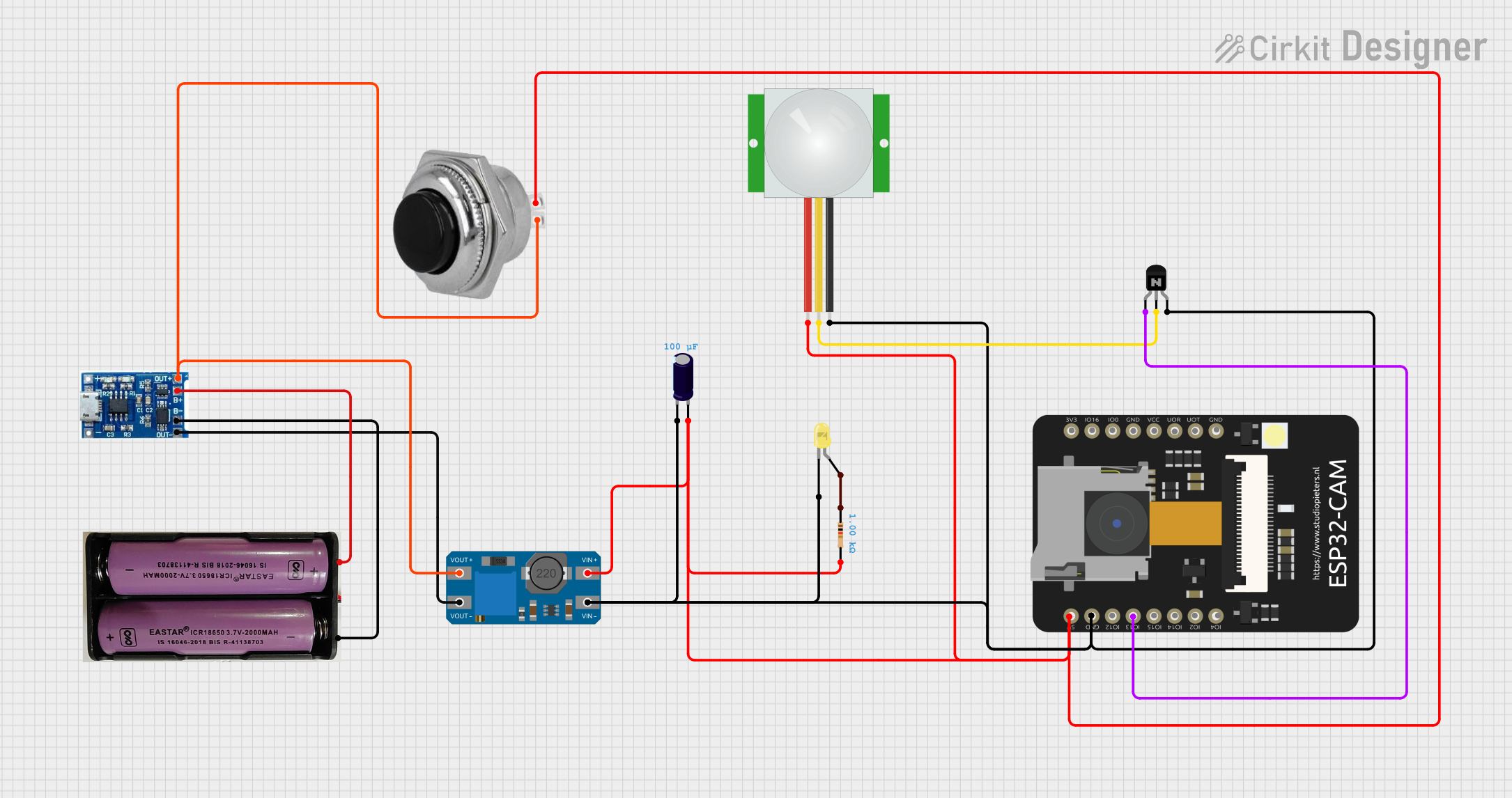 Open Project in Cirkit Designer
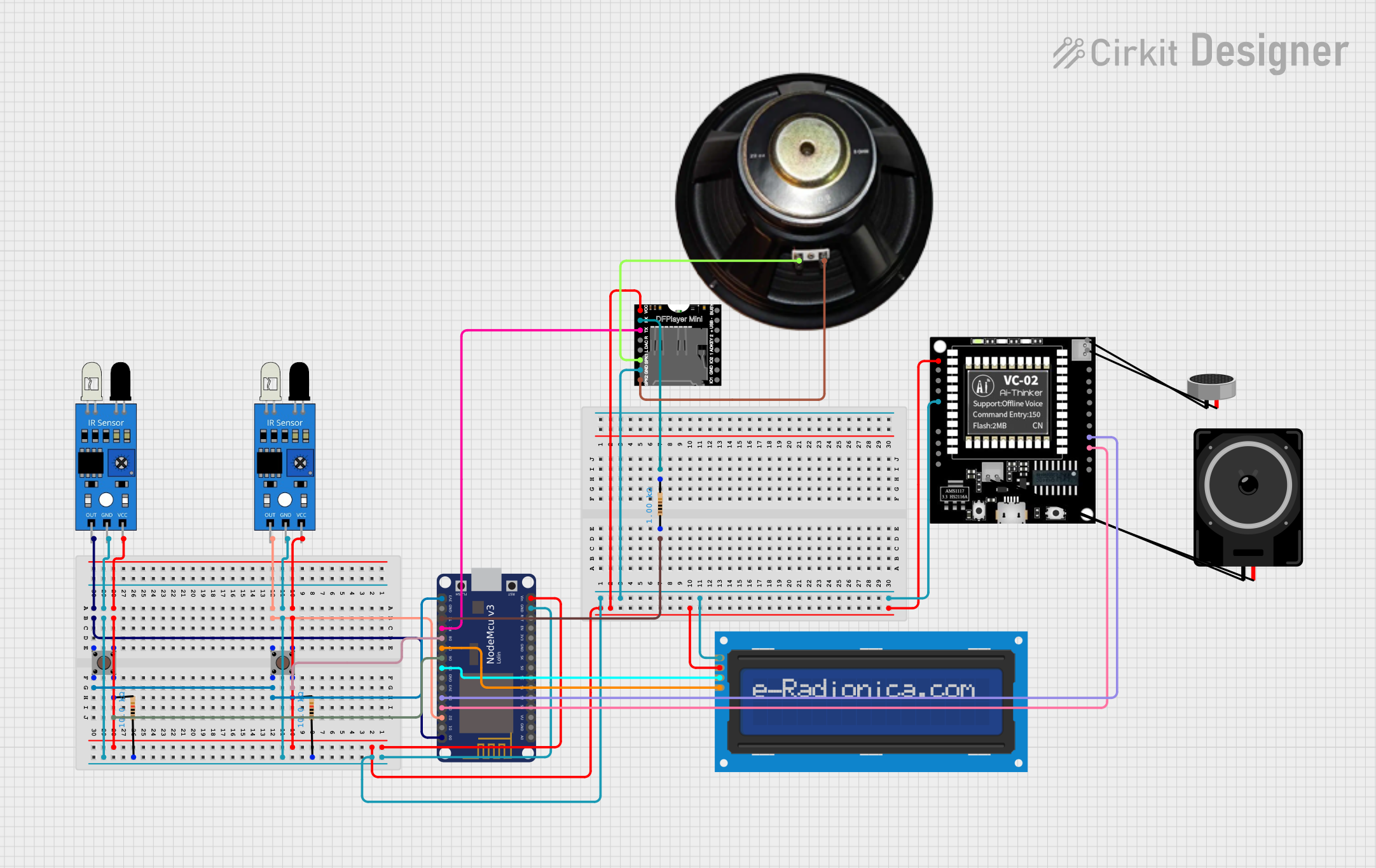 Open Project in Cirkit Designer
Explore Projects Built with KidBright32 V1.3
Open Project in Cirkit DesignerOpen Project in Cirkit DesignerOpen Project in Cirkit DesignerOpen Project in Cirkit DesignerCommon Applications and Use Cases
- STEM education and electronics learning
- IoT (Internet of Things) projects
- Prototyping and experimentation
- Robotics and automation
- Sensor-based applications (e.g., temperature, light, motion detection)
Technical Specifications
Key Technical Details
| Specification | Value |
|---|---|
| Microcontroller | ESP32 (dual-core, 32-bit, 240 MHz) |
| Flash Memory | 4 MB |
| RAM | 520 KB |
| Operating Voltage | 3.3V |
| Input Voltage Range | 5V (via USB) |
| Connectivity | Wi-Fi 802.11 b/g/n, Bluetooth 4.2 |
| Built-in Sensors | Light sensor, temperature sensor |
| GPIO Pins | 12 (digital and analog capable) |
| Display | 16x2 LED matrix |
| Programming Interfaces | USB, KidBright IDE, Arduino IDE, Python |
| Dimensions | 60 mm x 40 mm |
Pin Configuration and Descriptions
| Pin Number | Pin Name | Description |
|---|---|---|
| 1 | GND | Ground pin |
| 2 | 3V3 | 3.3V power output |
| 3 | GPIO0 | General-purpose I/O pin |
| 4 | GPIO1 | General-purpose I/O pin |
| 5 | GPIO2 | General-purpose I/O pin |
| 6 | GPIO3 | General-purpose I/O pin |
| 7 | SDA | I2C data line |
| 8 | SCL | I2C clock line |
| 9 | TX | UART transmit pin |
| 10 | RX | UART receive pin |
| 11 | VIN | Input voltage (5V via USB) |
| 12 | RST | Reset pin |
Usage Instructions
How to Use the KidBright32 V1.3 in a Circuit
Powering the Board:
- Connect the board to a computer or USB power source using a micro-USB cable.
- Ensure the input voltage is 5V to avoid damaging the board.
Programming the Board:
- Install the KidBright IDE or Arduino IDE on your computer.
- Select the appropriate board and port in the IDE settings.
- Write your program and upload it to the board via USB.
Connecting Sensors and Actuators:
- Use the GPIO pins to connect external sensors or actuators.
- Refer to the pin configuration table to identify the correct pins for your application.
Using Built-in Sensors:
- The board includes a light sensor and a temperature sensor.
- These sensors can be accessed directly in your code using predefined libraries.
Important Considerations and Best Practices
- Always check the voltage and current ratings of connected components to avoid damage.
- Use pull-up or pull-down resistors when working with GPIO pins in digital mode.
- Avoid shorting pins or connecting them to voltages higher than 3.3V.
- Ensure proper grounding when connecting external devices.
Example Code for Arduino IDE
Below is an example code snippet to read the built-in light sensor and display the value on the LED matrix:
#include <Wire.h>
#include <KidBright32.h>

// Initialize the KidBright32 board
KidBright32 kb;

void setup() {
  kb.begin(); // Initialize the board
}

void loop() {
  int lightValue = kb.readLightSensor(); // Read light sensor value

  // Display the light value on the LED matrix
  kb.displayNumber(lightValue);

  delay(500); // Wait for 500ms before the next reading
}
Troubleshooting and FAQs
Common Issues and Solutions
Board Not Detected by Computer:
- Ensure the USB cable is properly connected and functional.
- Install the necessary USB drivers for the KidBright32 board.
Program Fails to Upload:
- Check that the correct board and port are selected in the IDE.
- Press and hold the reset button while uploading the program.
Sensors Not Responding:
- Verify the connections and ensure the sensors are properly powered.
- Use the built-in diagnostic tools in the KidBright IDE to test sensor functionality.
Wi-Fi or Bluetooth Not Working:
- Ensure the correct credentials or pairing settings are used in your code.
- Check for interference or weak signal strength in your environment.
FAQs
Q: Can I use the KidBright32 with Python?
A: Yes, the KidBright32 supports MicroPython, allowing you to program it using Python.
Q: What is the maximum current output of the GPIO pins?
A: Each GPIO pin can source or sink up to 12 mA. Avoid exceeding this limit to prevent damage.
Q: Can I power the board using a battery?
A: Yes, you can use a 3.7V LiPo battery connected to the VIN and GND pins.
Q: Is the KidBright32 compatible with Arduino shields?
A: No, the KidBright32 does not have the same pin layout as Arduino boards, so it is not directly compatible with Arduino shields.
This concludes the documentation for the KidBright32 V1.3. For further assistance, refer to the official Gravitech resources or community forums.