Cirkit Designer Logo
Cirkit Designer
Your all-in-one circuit design IDE
Home / 
Component Documentation

How to Use TVS-Diode SMBJ24A: Examples, Pinouts, and Specs

Image of TVS-Diode SMBJ24A
Cirkit Designer LogoDesign with TVS-Diode SMBJ24A in Cirkit Designer

Introduction

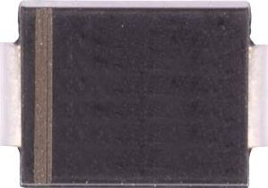
The SMBJ24A is a Transient Voltage Suppressor (TVS) diode manufactured by Diodes Incorporated. It is specifically designed to protect sensitive electronic components from voltage spikes and transients caused by electrostatic discharge (ESD), lightning, and other overvoltage conditions. The SMBJ24A can clamp voltages up to 24V, making it ideal for safeguarding power supply circuits, data lines, and other critical electronic systems.

Explore Projects Built with TVS-Diode SMBJ24A

Use Cirkit Designer to design, explore, and prototype these projects online. Some projects support real-time simulation. Click "Open Project" to start designing instantly!
Modular Power Distribution System with Multiple SMPS Units and 120V Outlet
Image of Cellion-Tesla: A project utilizing TVS-Diode SMBJ24A in a practical application
This circuit is designed to convert 240V AC power to both 12V and 24V DC outputs using multiple SMPS units. Terminal blocks are used to organize and distribute the power, while a 120V outlet provides additional AC power access. The circuit is likely used for powering various electronic devices that require different voltage levels.
Cirkit Designer LogoOpen Project in Cirkit Designer
T-Beam with I2C OLED Display Interface
Image of MQTT_Node: A project utilizing TVS-Diode SMBJ24A in a practical application
This circuit connects a T-Beam microcontroller board with an OLED 128x64 I2C Monochrome Display. The T-Beam's I2C pins (SDA and SCL) are wired to the corresponding SDA and SCK pins on the OLED display, allowing for communication between the microcontroller and the display. Power and ground connections are also established, with the display's VDD connected to the T-Beam's 3V3 output, and GND to GND, to complete the power circuit for the display.
Cirkit Designer LogoOpen Project in Cirkit Designer
Arduino-Controlled 4-Channel RF Decoder Data Display with I2C LCD Interface
Image of FYP: A project utilizing TVS-Diode SMBJ24A in a practical application
This circuit comprises an Arduino UNO microcontroller interfaced with four 2-to-12 series CMOS decoders, a 433 MHz RF receiver module, four 1MΩ resistors, four red LEDs, and a 20x4 I2C LCD display. The Arduino reads 3-bit data from each decoder, which are likely receiving signals from the RF receiver, and displays the binary data on the LCD. The LEDs are connected to the decoders' VT (valid transmission) pins, indicating successful data reception, and the entire circuit is powered by a 5V DC source.
Cirkit Designer LogoOpen Project in Cirkit Designer
Stepper Motor Control System with TB6600 Driver and DKC-1A Controller
Image of Copy of Copy of PLC-Based Step Motor Speed and Direction Control System: A project utilizing TVS-Diode SMBJ24A in a practical application
This circuit controls a bipolar stepper motor using a tb6600 micro stepping motor driver and a DKC-1A stepper motor controller. The system is powered by a 24VDC power supply and includes a relay module for additional control functionalities.
Cirkit Designer LogoOpen Project in Cirkit Designer

Explore Projects Built with TVS-Diode SMBJ24A

Use Cirkit Designer to design, explore, and prototype these projects online. Some projects support real-time simulation. Click "Open Project" to start designing instantly!
Image of Cellion-Tesla: A project utilizing TVS-Diode SMBJ24A in a practical application
Modular Power Distribution System with Multiple SMPS Units and 120V Outlet
This circuit is designed to convert 240V AC power to both 12V and 24V DC outputs using multiple SMPS units. Terminal blocks are used to organize and distribute the power, while a 120V outlet provides additional AC power access. The circuit is likely used for powering various electronic devices that require different voltage levels.
Cirkit Designer LogoOpen Project in Cirkit Designer
Image of MQTT_Node: A project utilizing TVS-Diode SMBJ24A in a practical application
T-Beam with I2C OLED Display Interface
This circuit connects a T-Beam microcontroller board with an OLED 128x64 I2C Monochrome Display. The T-Beam's I2C pins (SDA and SCL) are wired to the corresponding SDA and SCK pins on the OLED display, allowing for communication between the microcontroller and the display. Power and ground connections are also established, with the display's VDD connected to the T-Beam's 3V3 output, and GND to GND, to complete the power circuit for the display.
Cirkit Designer LogoOpen Project in Cirkit Designer
Image of FYP: A project utilizing TVS-Diode SMBJ24A in a practical application
Arduino-Controlled 4-Channel RF Decoder Data Display with I2C LCD Interface
This circuit comprises an Arduino UNO microcontroller interfaced with four 2-to-12 series CMOS decoders, a 433 MHz RF receiver module, four 1MΩ resistors, four red LEDs, and a 20x4 I2C LCD display. The Arduino reads 3-bit data from each decoder, which are likely receiving signals from the RF receiver, and displays the binary data on the LCD. The LEDs are connected to the decoders' VT (valid transmission) pins, indicating successful data reception, and the entire circuit is powered by a 5V DC source.
Cirkit Designer LogoOpen Project in Cirkit Designer
Image of Copy of Copy of PLC-Based Step Motor Speed and Direction Control System: A project utilizing TVS-Diode SMBJ24A in a practical application
Stepper Motor Control System with TB6600 Driver and DKC-1A Controller
This circuit controls a bipolar stepper motor using a tb6600 micro stepping motor driver and a DKC-1A stepper motor controller. The system is powered by a 24VDC power supply and includes a relay module for additional control functionalities.
Cirkit Designer LogoOpen Project in Cirkit Designer

Common Applications

  • Protection of power supply circuits from voltage surges
  • Safeguarding data lines in communication systems
  • ESD protection in consumer electronics
  • Overvoltage protection in industrial equipment
  • Automotive electronics to prevent damage from load dumps

Technical Specifications

Key Technical Details

Parameter Value
Manufacturer Diodes Incorporated
Part Number SMBJ24A
Breakdown Voltage (VBR) 26.7V (minimum) to 29.5V (maximum)
Working Peak Reverse Voltage (VRWM) 24V
Clamping Voltage (VC) 38.9V (maximum) at 1A
Peak Pulse Current (IPP) 15.4A (maximum)
Power Dissipation (PPP) 600W (10/1000 µs waveform)
Reverse Leakage Current (IR) 1µA (maximum) at 24V
Package Type SMB (DO-214AA)
Operating Temperature Range -55°C to +150°C
Compliance Standards IEC 61000-4-2 (ESD), RoHS

Pin Configuration and Descriptions

The SMBJ24A is a two-terminal device with the following pin configuration:

Pin Number Pin Name Description
1 Anode Positive terminal of the diode
2 Cathode Negative terminal of the diode

The SMB package (DO-214AA) is a surface-mount package with polarity markings to indicate the cathode.

Usage Instructions

How to Use the SMBJ24A in a Circuit

  1. Identify the Voltage to Protect Against: Ensure the working peak reverse voltage (VRWM) of 24V is suitable for your application.
  2. Connect the Diode Across the Circuit:
    • Connect the anode to the ground (GND) of the circuit.
    • Connect the cathode to the voltage line to be protected.
  3. Verify Polarity: The cathode is typically marked with a stripe on the package. Incorrect polarity can result in improper operation or damage.
  4. Ensure Proper Soldering: Use appropriate soldering techniques for the SMB package to ensure a reliable connection.
  5. Add Series Resistance if Necessary: In some cases, a small series resistor may be added to limit current during transient events.

Important Considerations and Best Practices

  • Thermal Management: Ensure adequate heat dissipation, as the diode can dissipate up to 600W during transient events.
  • Voltage Selection: Do not exceed the maximum clamping voltage (VC) of 38.9V to avoid damage to the diode or the circuit.
  • ESD Compliance: The SMBJ24A complies with IEC 61000-4-2 standards, making it suitable for ESD-sensitive applications.
  • Parallel Configuration: For higher power dissipation, multiple SMBJ24A diodes can be connected in parallel, but ensure proper current sharing.

Example Circuit with Arduino UNO

The SMBJ24A can be used to protect the power supply input of an Arduino UNO from voltage spikes. Below is an example:

/*
  Example Circuit: Protecting Arduino UNO Power Input with SMBJ24A
  - The SMBJ24A is connected across the 5V and GND pins of the Arduino UNO.
  - This protects the Arduino from voltage spikes on the 5V line.
*/

// No specific code is required for the SMBJ24A, as it operates passively.
// Ensure the SMBJ24A is connected as follows:
// Cathode (marked with a stripe) -> 5V pin of Arduino UNO
// Anode -> GND pin of Arduino UNO

// Note: The SMBJ24A will clamp any voltage spikes above 24V to protect the Arduino.

Troubleshooting and FAQs

Common Issues and Solutions

Issue Possible Cause Solution
Diode is not clamping voltage Incorrect polarity connection Verify the anode and cathode connections.
Excessive heat during operation Prolonged overvoltage or high current Check the circuit design and ensure transient events are within the diode's limits.
Circuit not protected from spikes Insufficient clamping voltage rating Ensure the SMBJ24A's clamping voltage is appropriate for your application.
Reverse leakage current is too high Operating voltage exceeds VRWM Verify the operating voltage is within 24V.

FAQs

  1. Can the SMBJ24A protect against lightning surges?
    Yes, the SMBJ24A can handle transient events such as lightning surges, provided the peak pulse current (IPP) does not exceed 15.4A.

  2. Can I use the SMBJ24A for AC circuits?
    The SMBJ24A is designed for DC circuits. For AC applications, consider using a bidirectional TVS diode.

  3. What happens if the diode is connected in reverse?
    If connected in reverse, the diode will not function as intended and may fail to protect the circuit.

  4. How do I test if the SMBJ24A is working?
    Use a multimeter in diode mode to check the forward voltage drop. A reading of approximately 0.7V indicates proper operation.

By following this documentation, you can effectively integrate the SMBJ24A into your designs and ensure reliable protection against voltage transients.