
How to Use Power Meter Modbus: Examples, Pinouts, and Specs
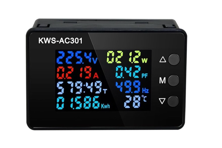
 Design with Power Meter Modbus in Cirkit Designer
Introduction
The Power Meter Modbus is a versatile device designed to measure electrical power consumption and communicate the data using the Modbus protocol. This enables seamless integration into industrial and commercial systems for remote monitoring and control. It is widely used in energy management systems, industrial automation, and building management systems to track energy usage, optimize power consumption, and reduce operational costs.
Explore Projects Built with Power Meter Modbus
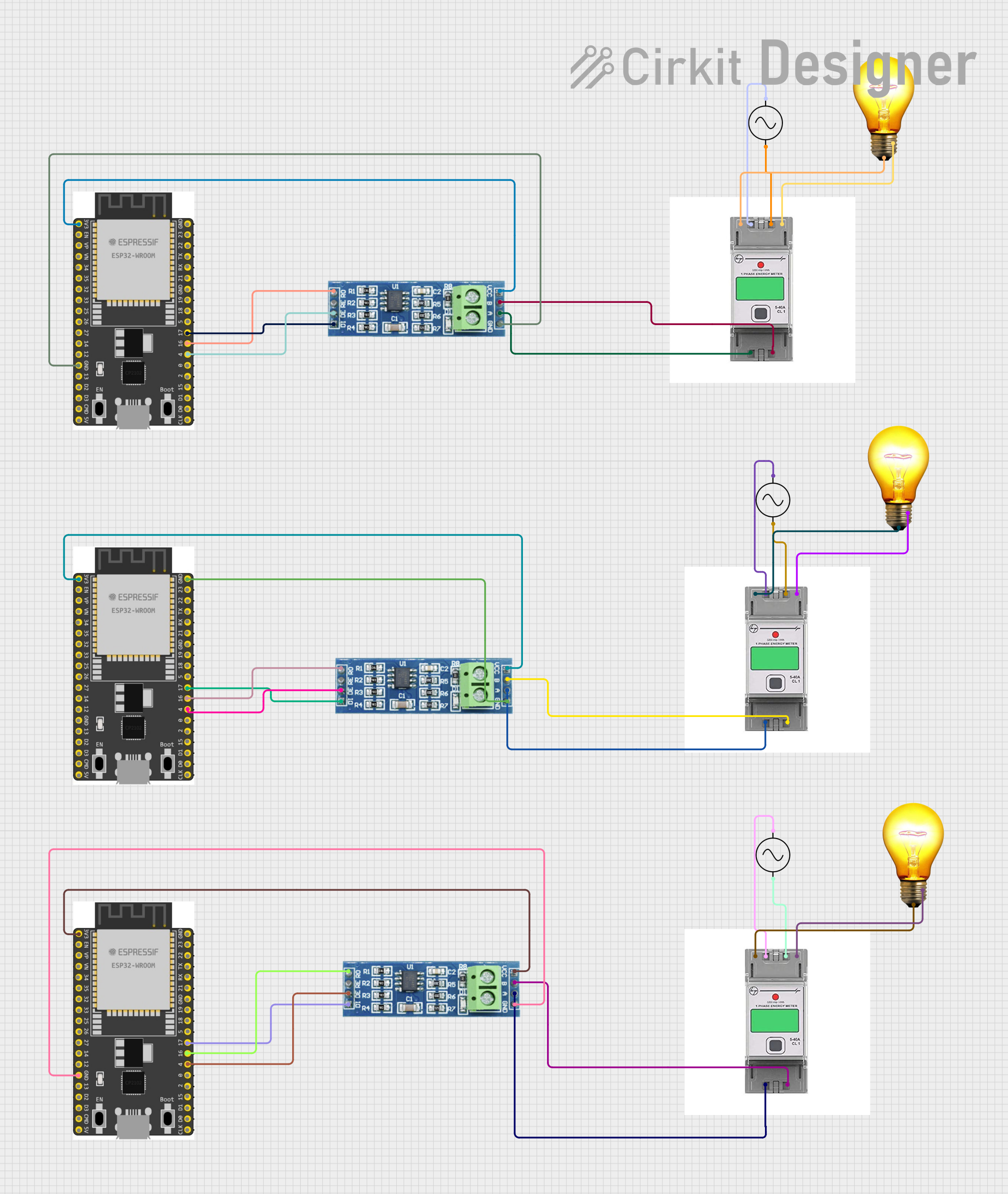 Open Project in Cirkit Designer
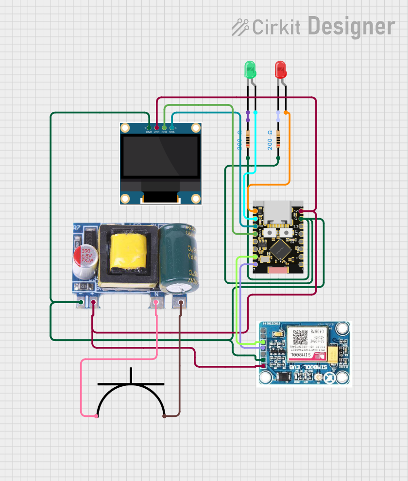 Open Project in Cirkit Designer
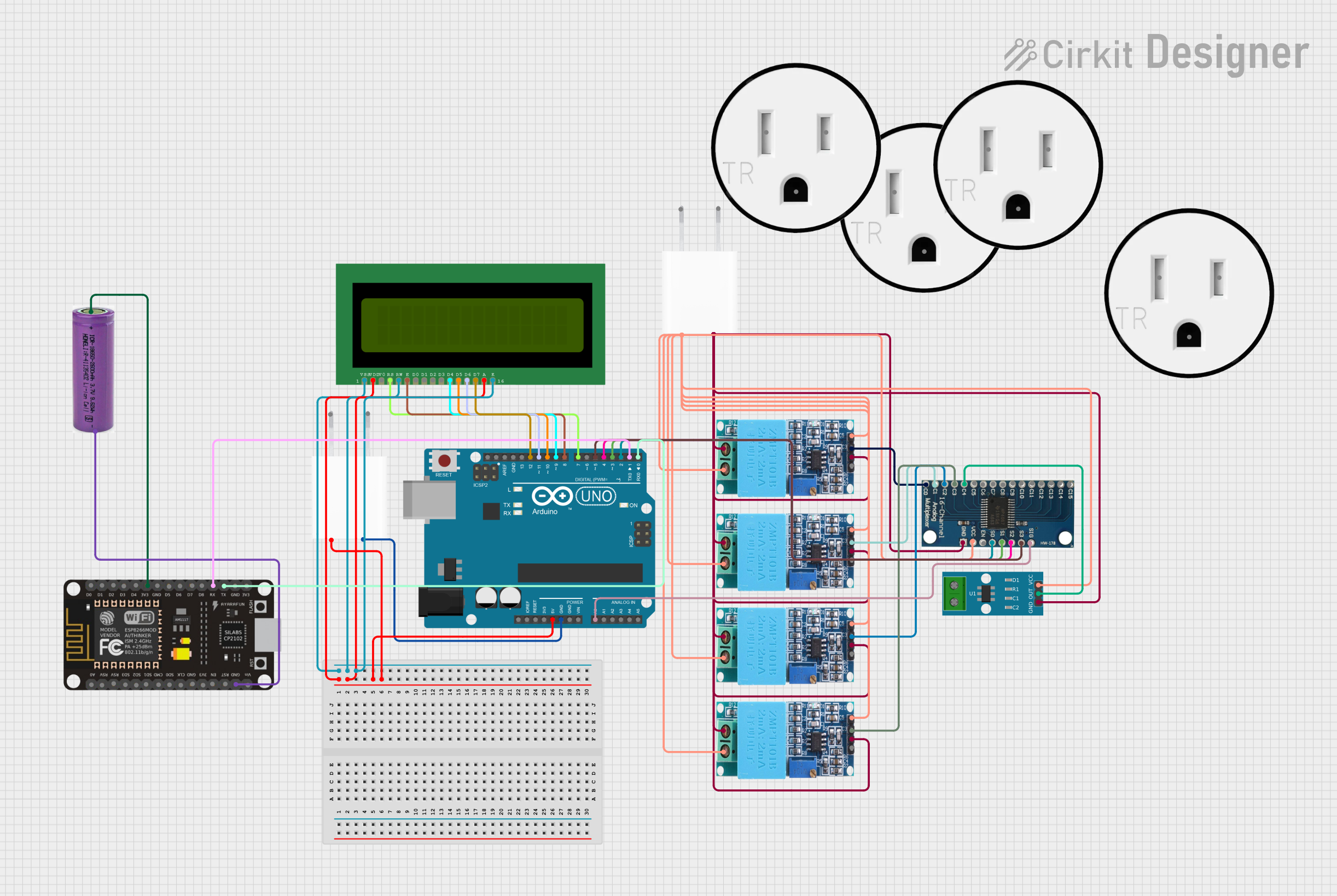 Open Project in Cirkit Designer
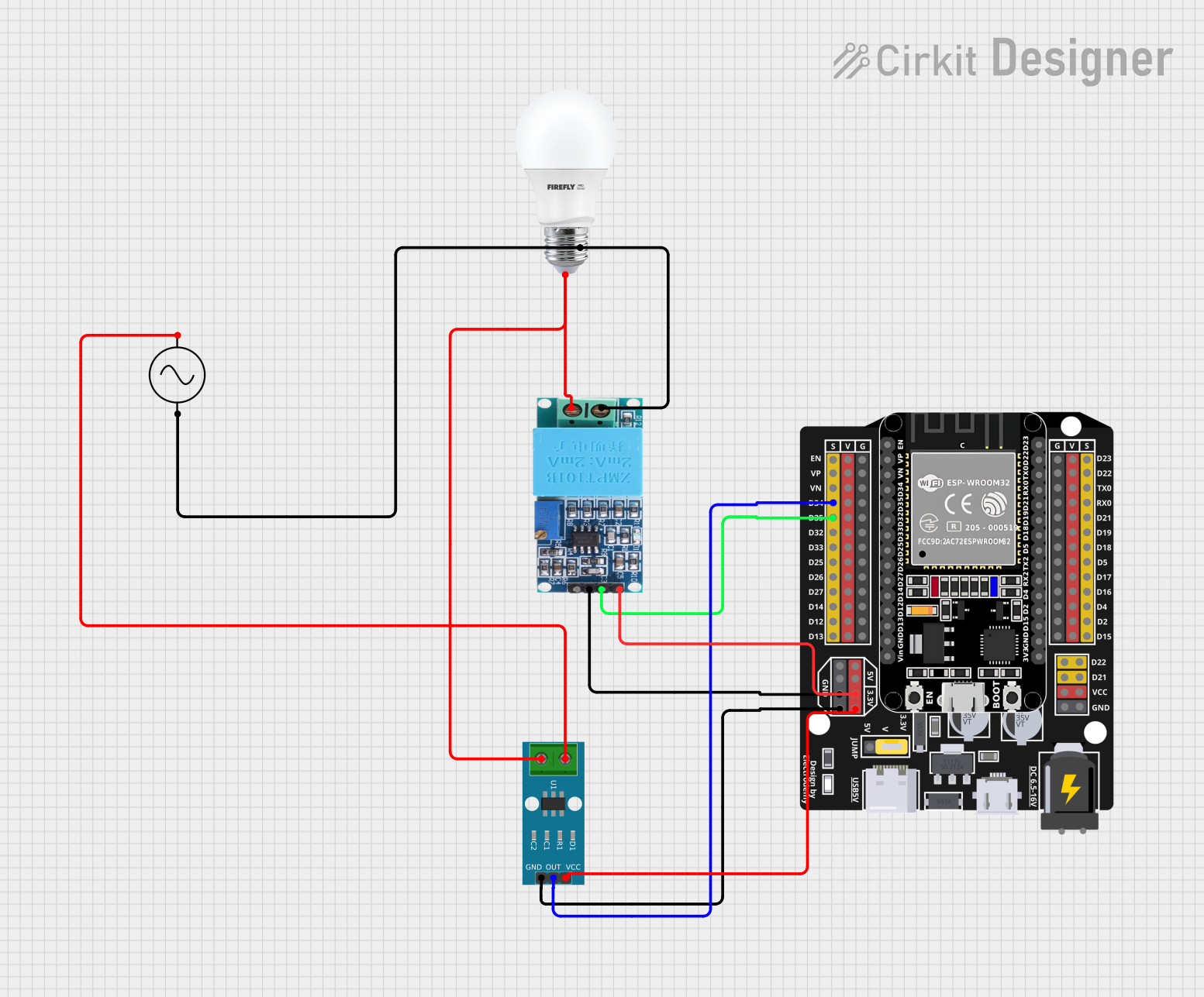 Open Project in Cirkit Designer
Explore Projects Built with Power Meter Modbus
Open Project in Cirkit DesignerOpen Project in Cirkit DesignerOpen Project in Cirkit DesignerOpen Project in Cirkit DesignerCommon Applications
- Energy monitoring in industrial plants and factories
- Power consumption tracking in commercial buildings
- Integration into SCADA (Supervisory Control and Data Acquisition) systems
- Load management and optimization in renewable energy systems
- Remote monitoring of electrical systems in data centers
Technical Specifications
Key Technical Details
| Parameter | Specification |
|---|---|
| Supply Voltage | 85-265V AC or 100-300V DC |
| Power Consumption | < 5W |
| Measurement Voltage Range | 0-300V AC |
| Measurement Current Range | 0-5A (via CT) |
| Communication Protocol | Modbus RTU (RS-485) |
| Baud Rate | 9600 bps (default), configurable |
| Data Format | 8N1 (8 data bits, no parity, 1 stop bit) |
| Accuracy | ±0.5% for voltage and current |
| Operating Temperature | -25°C to 70°C |
| Dimensions | 96mm x 96mm x 65mm |
Pin Configuration and Descriptions
Power Supply and Measurement Terminals
| Pin Number | Label | Description |
|---|---|---|
| 1 | L | Live wire for power supply |
| 2 | N | Neutral wire for power supply |
| 3 | V+ | Voltage measurement input (Phase) |
| 4 | V- | Voltage measurement input (Neutral) |
| 5 | I+ | Current transformer (CT) input (+) |
| 6 | I- | Current transformer (CT) input (-) |
Communication Terminals
| Pin Number | Label | Description |
|---|---|---|
| 7 | A | RS-485 Modbus communication (A) |
| 8 | B | RS-485 Modbus communication (B) |
| 9 | GND | Ground for RS-485 communication |
Usage Instructions
How to Use the Power Meter Modbus in a Circuit
- Power Supply Connection: Connect the live (L) and neutral (N) wires to pins 1 and 2, respectively, to power the device.
- Voltage Measurement: Connect the voltage measurement inputs (V+ and V-) to the phase and neutral of the circuit you want to monitor.
- Current Measurement: Use a current transformer (CT) to measure current. Connect the CT's output to the I+ and I- terminals.
- Communication Setup: Connect the RS-485 communication lines (A and B) to your Modbus master device (e.g., PLC, SCADA system, or Arduino).
- Configuration: Set the Modbus address, baud rate, and other communication parameters using the device's interface or configuration software.
Important Considerations
- Ensure the CT is properly rated for the current range of the monitored circuit.
- Use shielded twisted-pair cables for RS-485 communication to minimize noise.
- Terminate the RS-485 bus with a 120-ohm resistor at both ends for reliable communication.
- Verify that the Modbus master device is configured with the correct baud rate, parity, and stop bits to match the power meter.
Example: Connecting to an Arduino UNO
Below is an example of how to read data from the Power Meter Modbus using an Arduino UNO and an RS-485 module.
Arduino Code
#include <ModbusMaster.h>

// Instantiate ModbusMaster object
ModbusMaster node;

// RS-485 communication pins
#define RE_PIN 2  // Receiver Enable pin
#define DE_PIN 3  // Driver Enable pin

void preTransmission() {
  digitalWrite(RE_PIN, HIGH); // Enable RS-485 transmitter
  digitalWrite(DE_PIN, HIGH);
}

void postTransmission() {
  digitalWrite(RE_PIN, LOW);  // Disable RS-485 transmitter
  digitalWrite(DE_PIN, LOW);
}

void setup() {
  // Initialize serial communication
  Serial.begin(9600);
  Serial.println("Power Meter Modbus Example");

  // Initialize RS-485 control pins
  pinMode(RE_PIN, OUTPUT);
  pinMode(DE_PIN, OUTPUT);
  digitalWrite(RE_PIN, LOW);
  digitalWrite(DE_PIN, LOW);

  // Initialize Modbus communication
  node.begin(1, Serial); // Modbus ID 1
  node.preTransmission(preTransmission);
  node.postTransmission(postTransmission);
}

void loop() {
  uint8_t result;
  uint16_t data[2];

  // Read voltage (register address 0x0000)
  result = node.readInputRegisters(0x0000, 2);
  if (result == node.ku8MBSuccess) {
    data[0] = node.getResponseBuffer(0); // Voltage value
    Serial.print("Voltage: ");
    Serial.println(data[0] / 100.0); // Assuming value is in 0.01V units
  } else {
    Serial.println("Failed to read voltage");
  }

  delay(1000); // Wait 1 second before next read
}
Notes:
- Replace
0x0000with the appropriate Modbus register address for the parameter you want to read. - Ensure the RS-485 module is correctly connected to the Arduino's TX and RX pins.
Troubleshooting and FAQs
Common Issues
No Communication with Modbus Master
- Verify the RS-485 connections (A and B lines).
- Check that the Modbus address and communication parameters (baud rate, parity, stop bits) match between the power meter and the master device.
- Ensure proper termination of the RS-485 bus with 120-ohm resistors.
Incorrect Measurements
- Confirm that the voltage and current inputs are connected correctly.
- Ensure the CT is properly rated and installed in the correct orientation.
- Check for loose or faulty wiring.
Device Not Powering On
- Verify the power supply voltage is within the specified range (85-265V AC or 100-300V DC).
- Check for blown fuses or tripped breakers in the power supply circuit.
FAQs
Q: Can I use this power meter with a 24V DC power supply?
A: No, the power meter requires a supply voltage of 85-265V AC or 100-300V DC.
Q: What is the maximum cable length for RS-485 communication?
A: RS-485 supports cable lengths up to 1200 meters, but this depends on the baud rate and cable quality.
Q: How do I reset the Modbus address?
A: Refer to the device's user manual for instructions on resetting the Modbus address, typically done via a hardware button or configuration software.
Q: Can I monitor multiple circuits with one power meter?
A: No, this power meter is designed to monitor a single circuit. Use multiple meters for multiple circuits.