
How to Use SWITCH-MOMENTARY-2: Examples, Pinouts, and Specs
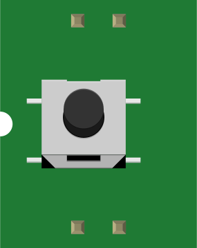
 Design with SWITCH-MOMENTARY-2 in Cirkit Designer
Introduction
The SWITCH-MOMENTARY-2 is a momentary push-button switch designed to close a circuit only while it is being pressed. Once released, the circuit is opened again. This type of switch is commonly used for temporary actions such as triggering a function, activating a device, or sending a signal in electronic circuits. Its simple design and functionality make it a versatile component in various applications.
Explore Projects Built with SWITCH-MOMENTARY-2
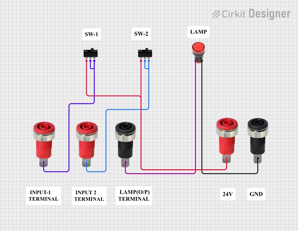 Open Project in Cirkit Designer
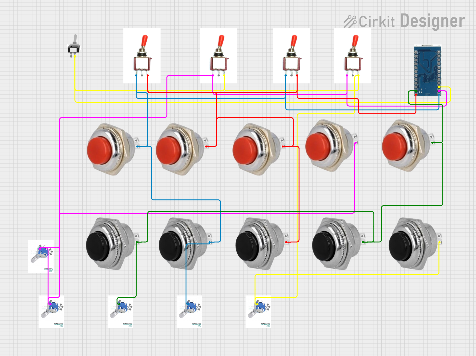 Open Project in Cirkit Designer
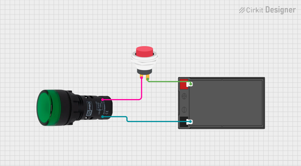 Open Project in Cirkit Designer
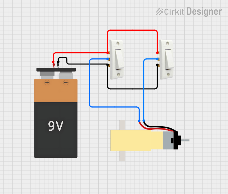 Open Project in Cirkit Designer
Explore Projects Built with SWITCH-MOMENTARY-2
Open Project in Cirkit DesignerOpen Project in Cirkit DesignerOpen Project in Cirkit DesignerOpen Project in Cirkit DesignerCommon Applications and Use Cases
- Reset buttons in electronic devices
- Triggering events in microcontroller-based projects
- Activating relays or other temporary circuits
- User input for control panels or interfaces
- Testing and debugging circuits
Technical Specifications
The SWITCH-MOMENTARY-2 is a compact and reliable component with the following specifications:
| Parameter | Value |
|---|---|
| Switch Type | Momentary (Normally Open) |
| Operating Voltage | 3V to 24V DC |
| Maximum Current | 50mA |
| Contact Resistance | ≤ 50 mΩ |
| Insulation Resistance | ≥ 100 MΩ |
| Operating Temperature | -20°C to +70°C |
| Mechanical Life | 100,000 cycles |
Pin Configuration and Descriptions
The SWITCH-MOMENTARY-2 typically has two pins, as described below:
| Pin | Description |
|---|---|
| Pin 1 | Connects to one side of the circuit (input) |
| Pin 2 | Connects to the other side of the circuit (output) |
Usage Instructions
How to Use the SWITCH-MOMENTARY-2 in a Circuit
- Identify the Pins: Locate the two pins of the switch. These are not polarized, so they can be connected in either orientation.
- Connect to the Circuit:
- Connect one pin to the power source or signal input.
- Connect the other pin to the load or signal output.
- Press to Activate: When the button is pressed, the circuit will close, allowing current to flow. Releasing the button will open the circuit.
Important Considerations and Best Practices
- Debouncing: Momentary switches can produce electrical noise or "bouncing" when pressed. Use a capacitor or software debouncing techniques to ensure stable operation in digital circuits.
- Current Limitation: Ensure the current through the switch does not exceed the maximum rating of 50mA to avoid damage.
- Mounting: Secure the switch properly to prevent mechanical stress on the pins during operation.
- Voltage Compatibility: Verify that the operating voltage of the circuit is within the switch's rated range (3V to 24V DC).
Example: Connecting to an Arduino UNO
The SWITCH-MOMENTARY-2 can be used as an input device for an Arduino UNO. Below is an example circuit and code to detect button presses:
Circuit Diagram
- Connect one pin of the switch to Arduino digital pin 2.
- Connect the other pin to the ground (GND).
- Use a pull-up resistor (10kΩ) between digital pin 2 and 5V to ensure a stable HIGH signal when the button is not pressed.
Arduino Code
// Define the pin connected to the momentary switch
const int buttonPin = 2;

// Variable to store the button state
int buttonState = 0;

void setup() {
  // Set the button pin as input with an internal pull-up resistor
  pinMode(buttonPin, INPUT_PULLUP);

  // Initialize serial communication for debugging
  Serial.begin(9600);
}

void loop() {
  // Read the state of the button (LOW when pressed, HIGH when released)
  buttonState = digitalRead(buttonPin);

  // Print the button state to the Serial Monitor
  if (buttonState == LOW) {
    Serial.println("Button Pressed");
  } else {
    Serial.println("Button Released");
  }

  // Add a small delay to avoid spamming the Serial Monitor
  delay(100);
}
Troubleshooting and FAQs
Common Issues and Solutions
Switch Not Responding
- Cause: Loose or incorrect connections.
- Solution: Verify that the switch pins are securely connected to the circuit.
Unstable or Erratic Behavior
- Cause: Switch bouncing.
- Solution: Add a capacitor (e.g., 0.1µF) across the switch pins or implement software debouncing in your code.
Switch Overheating
- Cause: Exceeding the maximum current rating.
- Solution: Ensure the current through the switch does not exceed 50mA.
No Signal Detected in Arduino
- Cause: Missing pull-up resistor.
- Solution: Use an external pull-up resistor or enable the internal pull-up resistor in the Arduino code.
FAQs
Q1: Can I use the SWITCH-MOMENTARY-2 with AC circuits?
A1: No, the SWITCH-MOMENTARY-2 is designed for low-voltage DC circuits only.
Q2: How do I debounce the switch in software?
A2: You can use a delay or a state-change detection algorithm in your code to filter out noise caused by bouncing.
Q3: What happens if I reverse the pins?
A3: The SWITCH-MOMENTARY-2 is non-polarized, so reversing the pins will not affect its operation.
Q4: Can I use this switch for high-power applications?
A4: No, this switch is rated for a maximum current of 50mA and is not suitable for high-power circuits. Use a relay or transistor to handle higher currents.