
How to Use Songle SLA-05VDC-SL-C 5V 30A Relay: Examples, Pinouts, and Specs
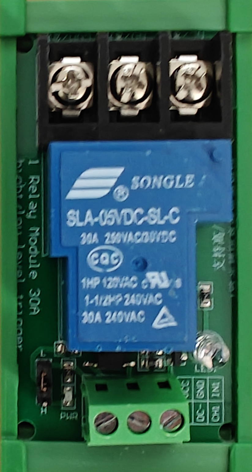
 Design with Songle SLA-05VDC-SL-C 5V 30A Relay in Cirkit Designer
Introduction
The Songle SLA-05VDC-SL-C is a compact electromagnetic relay designed to control high-power devices using a low-voltage signal. Operating at 5V DC, this relay can handle currents of up to 30A, making it ideal for applications requiring high-power switching. Its robust design and reliable performance make it a popular choice in automation, home appliances, industrial control systems, and DIY electronics projects.
Explore Projects Built with Songle SLA-05VDC-SL-C 5V 30A Relay
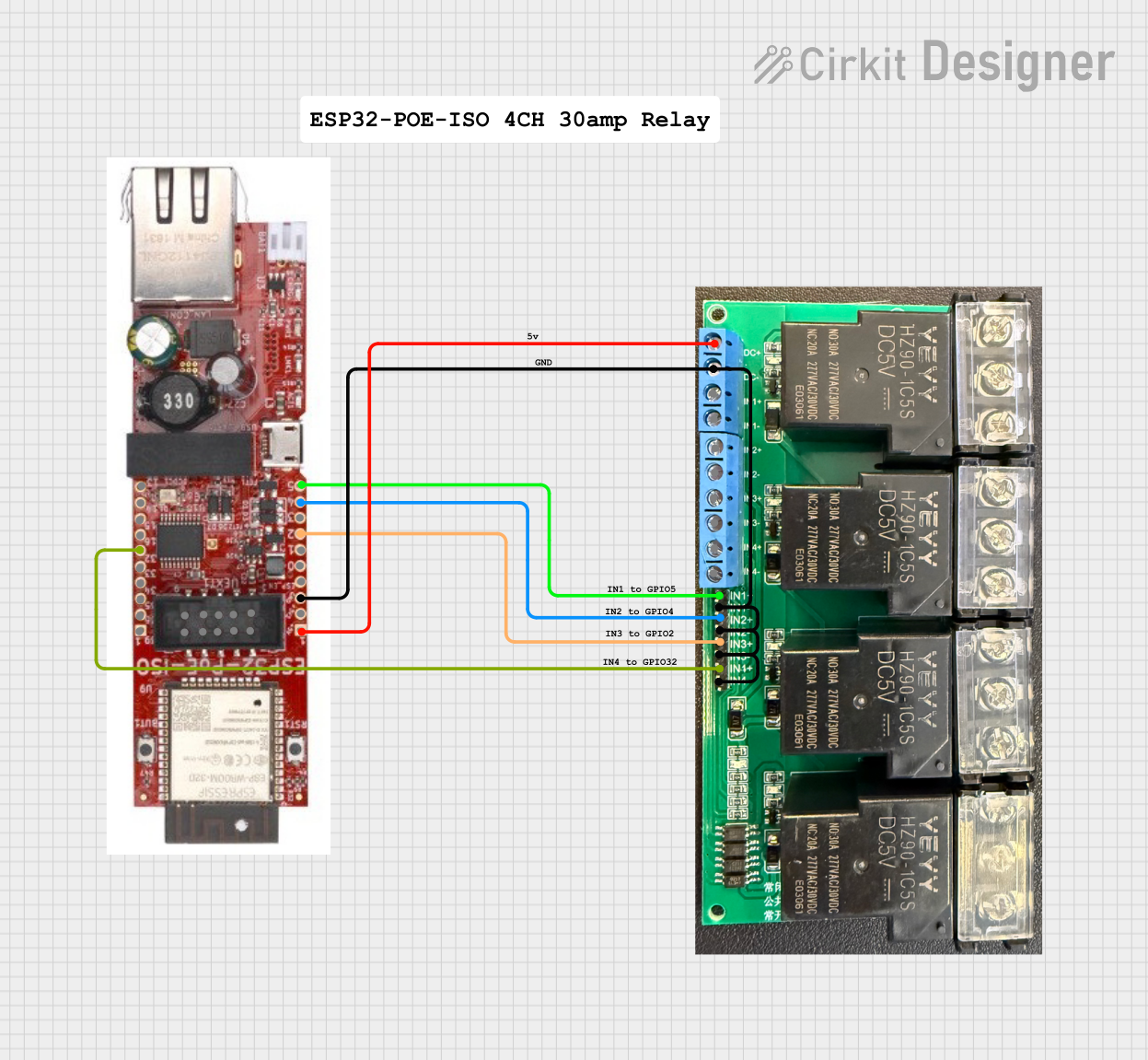 Open Project in Cirkit Designer
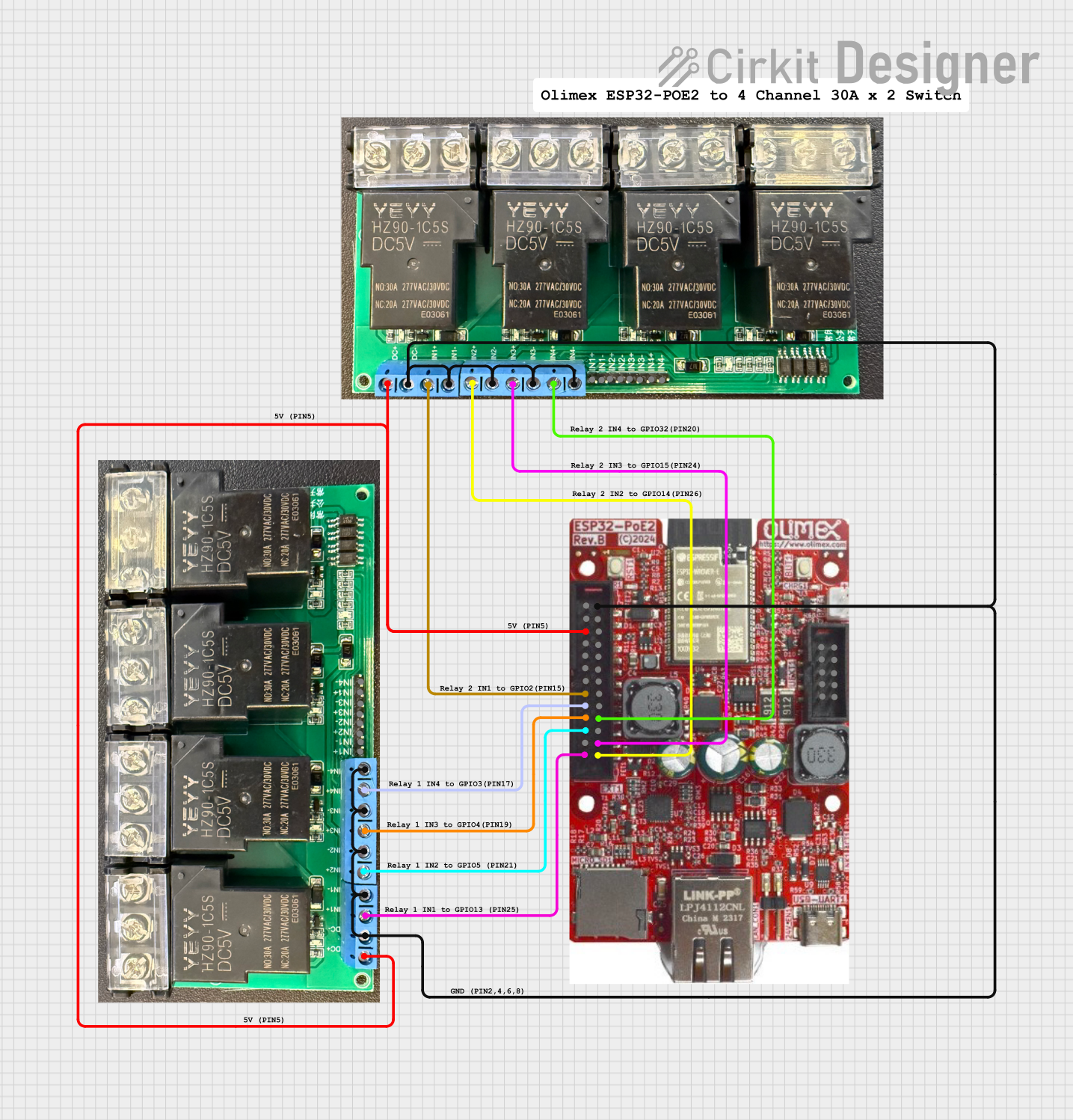 Open Project in Cirkit Designer
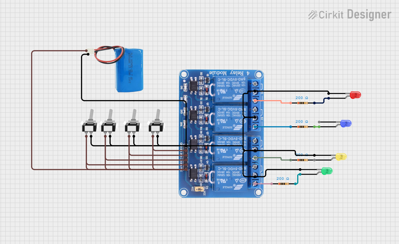 Open Project in Cirkit Designer
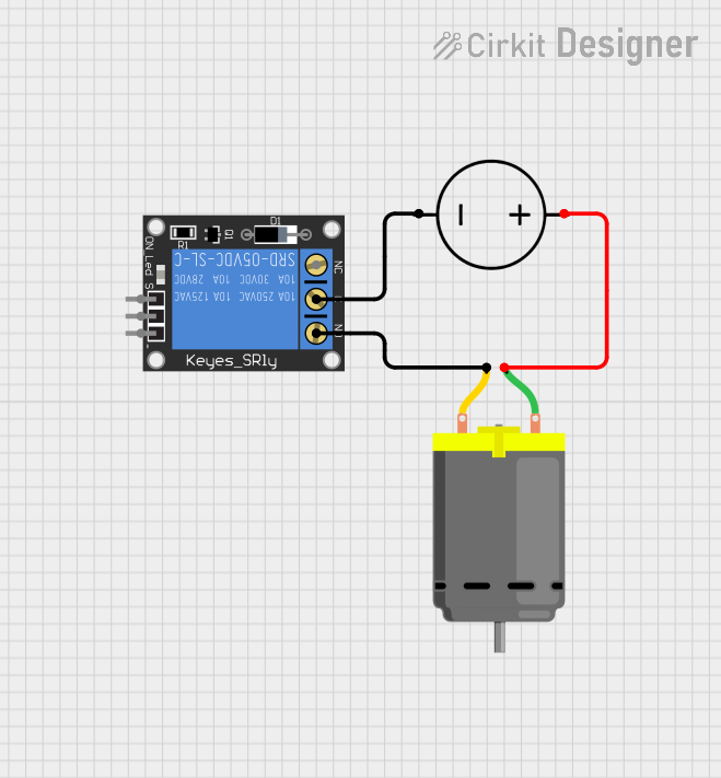 Open Project in Cirkit Designer
Explore Projects Built with Songle SLA-05VDC-SL-C 5V 30A Relay
Open Project in Cirkit DesignerOpen Project in Cirkit DesignerOpen Project in Cirkit DesignerOpen Project in Cirkit DesignerCommon Applications
- Home automation systems (e.g., controlling lights, fans, or appliances)
- Industrial control systems
- Motor control circuits
- DIY electronics and Arduino-based projects
- Power distribution and switching
Technical Specifications
Key Specifications
| Parameter | Value |
|---|---|
| Manufacturer | Songle |
| Part Number | SLA-05VDC-SL-C |
| Coil Voltage | 5V DC |
| Contact Current Rating | 30A |
| Contact Voltage Rating | 250V AC / 30V DC |
| Contact Configuration | SPDT (Single Pole Double Throw) |
| Coil Resistance | 70Ω ±10% |
| Operate Time | ≤10ms |
| Release Time | ≤5ms |
| Insulation Resistance | ≥100MΩ (at 500V DC) |
| Dielectric Strength | 1500V AC (1 min) |
| Operating Temperature | -40°C to +85°C |
| Dimensions | 19mm x 15.5mm x 15mm |
| Weight | ~15g |
Pin Configuration and Descriptions
The SLA-05VDC-SL-C relay has five pins, as described below:
| Pin Number | Name | Description |
|---|---|---|
| 1 | Coil (+) | Positive terminal of the relay coil. Connect to a 5V DC power source. |
| 2 | Coil (-) | Negative terminal of the relay coil. Connect to ground. |
| 3 | Common (COM) | Common terminal for the relay's switching contacts. |
| 4 | Normally Open (NO) | Open circuit when the relay is inactive; closed when the relay is activated. |
| 5 | Normally Closed (NC) | Closed circuit when the relay is inactive; open when the relay is activated. |
Usage Instructions
How to Use the SLA-05VDC-SL-C in a Circuit
- Power the Relay Coil: Connect the coil pins (1 and 2) to a 5V DC power source. Pin 1 should be connected to the positive terminal, and Pin 2 to ground.
- Connect the Load:
- Connect the device or load you want to control to the COM (Pin 3) and either the NO (Pin 4) or NC (Pin 5) terminals.
- Use the NO terminal if you want the load to be powered only when the relay is activated.
- Use the NC terminal if you want the load to be powered when the relay is inactive.
- Control the Relay: Use a microcontroller (e.g., Arduino) or a switch to control the relay coil. When the coil is energized, the relay switches from NC to NO.
Important Considerations
- Flyback Diode: Always connect a flyback diode (e.g., 1N4007) across the relay coil to protect your circuit from voltage spikes caused by the relay's inductive load.
- Power Ratings: Ensure the load connected to the relay does not exceed its rated current and voltage (30A, 250V AC / 30V DC).
- Isolation: Use optocouplers or transistor drivers if controlling the relay with a microcontroller to ensure electrical isolation.
- Heat Dissipation: For high-current applications, ensure proper ventilation or heat dissipation to prevent overheating.
Example: Connecting to an Arduino UNO
Below is an example of how to control the SLA-05VDC-SL-C relay using an Arduino UNO:
Circuit Diagram
- Connect the relay's Coil (+) pin to a digital output pin on the Arduino (e.g., Pin 7) through a transistor (e.g., 2N2222) and a 1kΩ base resistor.
- Connect the relay's Coil (-) pin to ground.
- Add a flyback diode across the relay coil.
- Connect the load to the COM and NO terminals of the relay.
Arduino Code
// Define the relay pin
const int relayPin = 7;

void setup() {
  // Set the relay pin as an output
  pinMode(relayPin, OUTPUT);
}

void loop() {
  // Turn the relay ON
  digitalWrite(relayPin, HIGH);
  delay(5000); // Keep the relay ON for 5 seconds

  // Turn the relay OFF
  digitalWrite(relayPin, LOW);
  delay(5000); // Keep the relay OFF for 5 seconds
}
Troubleshooting and FAQs
Common Issues and Solutions
Relay Not Switching:
- Cause: Insufficient voltage or current to the relay coil.
- Solution: Ensure the coil is powered with 5V DC and can draw the required current (~71mA).
Load Not Turning On/Off:
- Cause: Incorrect wiring of the load to the relay terminals.
- Solution: Verify the load is connected to the correct terminals (COM and NO/NC).
Microcontroller Resetting:
- Cause: Voltage spikes from the relay coil affecting the microcontroller.
- Solution: Add a flyback diode across the relay coil and ensure proper grounding.
Overheating:
- Cause: Load exceeding the relay's rated current or poor ventilation.
- Solution: Ensure the load is within the relay's specifications and provide adequate cooling.
FAQs
Q: Can I use this relay with a 3.3V microcontroller?
A: Yes, but you will need a transistor or relay driver circuit to step up the control signal to 5V.
Q: Is the relay suitable for switching DC motors?
A: Yes, but ensure the motor's starting current does not exceed the relay's 30A rating.
Q: Can I use this relay for AC loads?
A: Yes, the relay is rated for up to 250V AC at 30A. Ensure proper safety precautions when working with high voltages.
Q: Do I need a heatsink for high-current applications?
A: While the relay itself does not require a heatsink, ensure proper ventilation to prevent overheating in high-current scenarios.