
How to Use 24LC512: Examples, Pinouts, and Specs
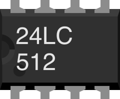
 Design with 24LC512 in Cirkit Designer
Introduction
The 24LC512 is a 512 Kbit (64 K x 8) I2C EEPROM manufactured by Microchip Technology. This non-volatile memory component is designed for applications requiring reliable data storage even when power is removed. It operates over a wide voltage range of 2.5V to 5.5V and communicates via a standard 2-wire I2C interface, making it easy to integrate into a variety of microcontroller-based systems.
Explore Projects Built with 24LC512
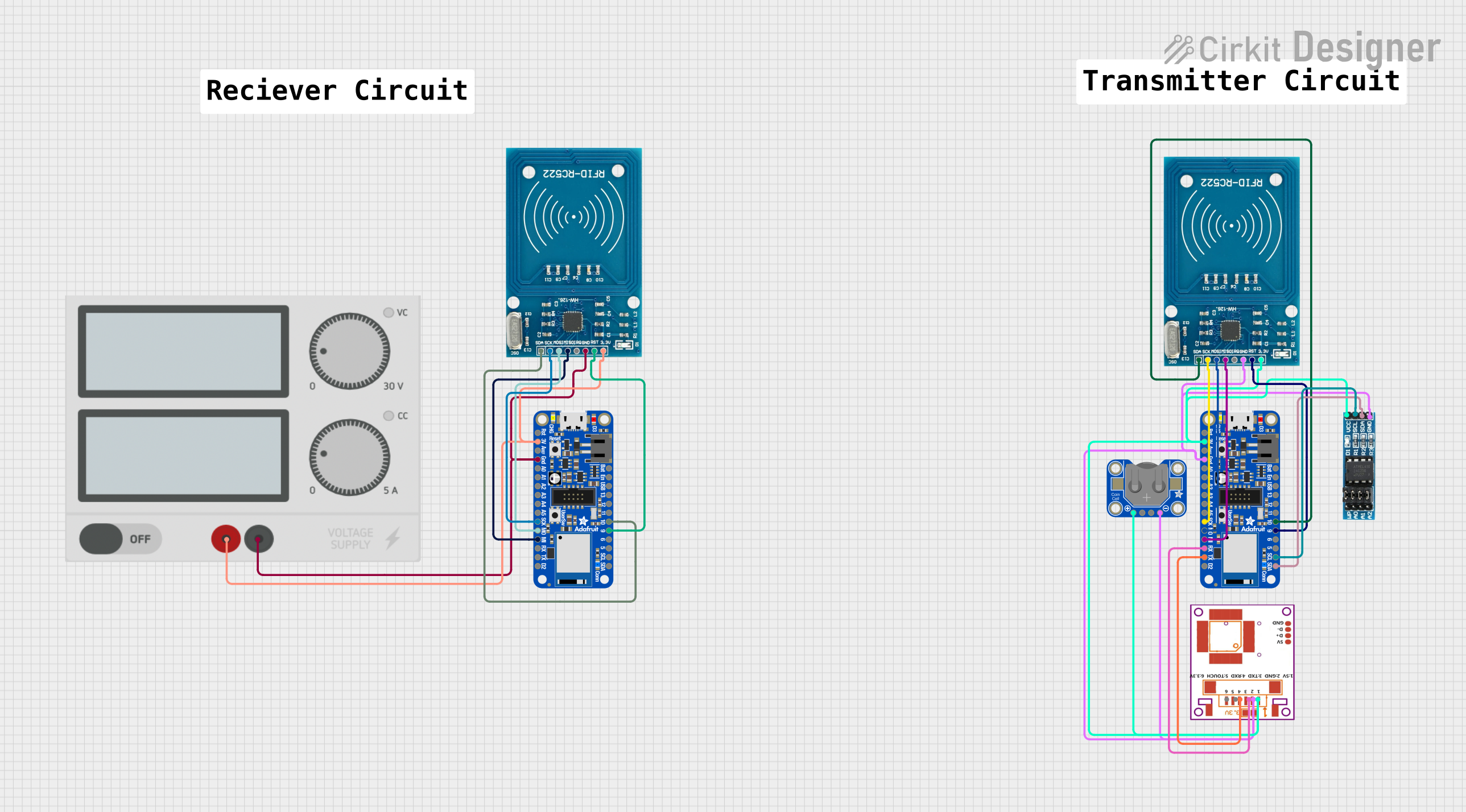 Open Project in Cirkit Designer
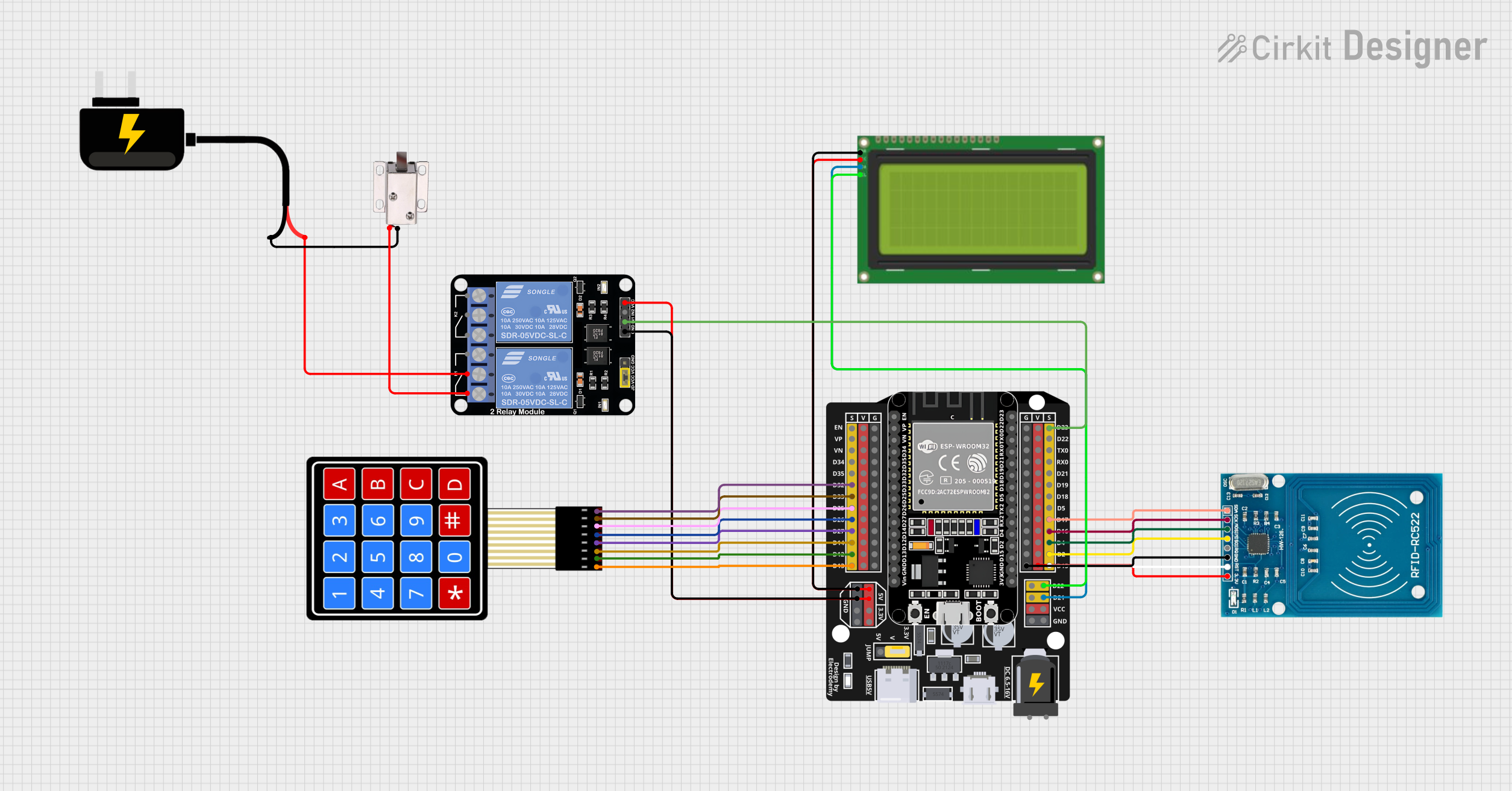 Open Project in Cirkit Designer
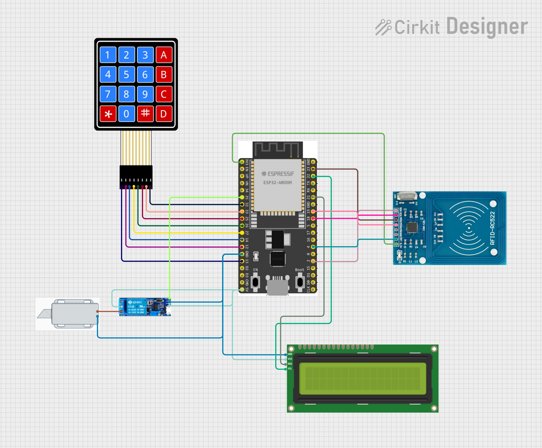 Open Project in Cirkit Designer
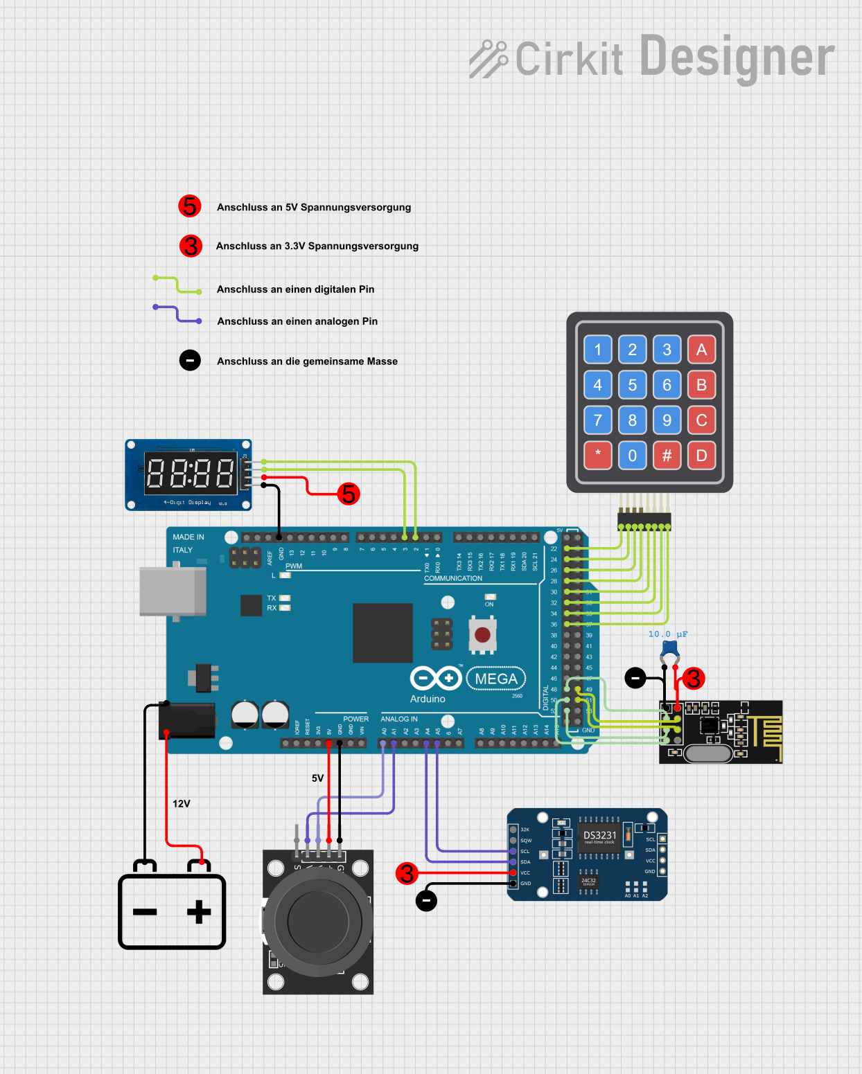 Open Project in Cirkit Designer
Explore Projects Built with 24LC512
Open Project in Cirkit DesignerOpen Project in Cirkit DesignerOpen Project in Cirkit DesignerOpen Project in Cirkit DesignerCommon Applications
- Data logging and storage in embedded systems
- Configuration and calibration data retention
- Consumer electronics requiring non-volatile memory
- Industrial control systems
- Medical devices and instrumentation
Technical Specifications
Key Specifications
| Parameter | Value |
|---|---|
| Memory Size | 512 Kbit (64 K x 8) |
| Interface | I2C (2-wire) |
| Operating Voltage Range | 2.5V to 5.5V |
| Maximum Clock Frequency | 400 kHz (Standard Mode) |
| Write Cycle Time | 5 ms (typical) |
| Endurance | 1,000,000 write cycles |
| Data Retention | > 200 years |
| Operating Temperature | -40°C to +85°C |
| Package Options | PDIP, SOIC, TSSOP, DFN |
Pin Configuration and Descriptions
The 24LC512 is available in an 8-pin package. Below is the pinout and description:
| Pin No. | Pin Name | Description |
|---|---|---|
| 1 | A0 | Device address input bit 0 (used for I2C addressing) |
| 2 | A1 | Device address input bit 1 (used for I2C addressing) |
| 3 | A2 | Device address input bit 2 (used for I2C addressing) |
| 4 | VSS | Ground (0V reference) |
| 5 | SDA | Serial Data (I2C bidirectional data line) |
| 6 | SCL | Serial Clock (I2C clock line) |
| 7 | WP | Write Protect (active high; disables write operations when tied to VCC) |
| 8 | VCC | Power supply (2.5V to 5.5V) |
Usage Instructions
How to Use the 24LC512 in a Circuit
- Power Supply: Connect the VCC pin to a power source within the range of 2.5V to 5.5V and the VSS pin to ground.
- I2C Addressing: Use the A0, A1, and A2 pins to set the I2C address of the device. These pins allow up to 8 devices to share the same I2C bus.
- Example: If all address pins are tied to ground, the 7-bit I2C address is
0x50.
- Example: If all address pins are tied to ground, the 7-bit I2C address is
- I2C Communication:
- Connect the SDA pin to the I2C data line and the SCL pin to the I2C clock line.
- Use pull-up resistors (typically 4.7 kΩ) on both the SDA and SCL lines.
- Write Protection: If write operations are not required, tie the WP pin to VCC to enable write protection.
- Data Transfer:
- Use an I2C master (e.g., a microcontroller) to send commands and data to the EEPROM.
- Follow the I2C protocol for reading and writing data.
Important Considerations
- Pull-Up Resistors: Ensure proper pull-up resistors are used on the SDA and SCL lines for reliable communication.
- Write Cycle Time: Allow a typical write cycle time of 5 ms before attempting to write new data.
- Address Conflicts: Avoid address conflicts when using multiple devices on the same I2C bus by configuring unique addresses using the A0, A1, and A2 pins.
- Write Protection: Use the WP pin to prevent accidental overwrites of critical data.
Example: Using 24LC512 with Arduino UNO
Below is an example of interfacing the 24LC512 with an Arduino UNO to write and read data.
Circuit Connections
| 24LC512 Pin | Arduino UNO Pin |
|---|---|
| VCC | 5V |
| VSS | GND |
| SDA | A4 |
| SCL | A5 |
| WP | GND |
| A0, A1, A2 | GND (I2C Address: 0x50) |
Arduino Code
#include <Wire.h> // Include the Wire library for I2C communication

#define EEPROM_I2C_ADDRESS 0x50 // I2C address of the 24LC512 (A0, A1, A2 = GND)

void setup() {
  Wire.begin(); // Initialize I2C communication
  Serial.begin(9600); // Initialize serial communication for debugging

  // Write a byte to EEPROM
  writeEEPROM(0x0000, 42); // Write the value 42 to memory address 0x0000
  delay(10); // Wait for the write cycle to complete

  // Read the byte back from EEPROM
  uint8_t data = readEEPROM(0x0000);
  Serial.print("Read data: ");
  Serial.println(data); // Print the read value
}

void loop() {
  // Nothing to do here
}

// Function to write a byte to the 24LC512
void writeEEPROM(uint16_t address, uint8_t data) {
  Wire.beginTransmission(EEPROM_I2C_ADDRESS);
  Wire.write((address >> 8) & 0xFF); // Send the high byte of the address
  Wire.write(address & 0xFF);        // Send the low byte of the address
  Wire.write(data);                  // Send the data byte
  Wire.endTransmission();            // End the I2C transmission
}

// Function to read a byte from the 24LC512
uint8_t readEEPROM(uint16_t address) {
  Wire.beginTransmission(EEPROM_I2C_ADDRESS);
  Wire.write((address >> 8) & 0xFF); // Send the high byte of the address
  Wire.write(address & 0xFF);        // Send the low byte of the address
  Wire.endTransmission();            // End the I2C transmission

  Wire.requestFrom(EEPROM_I2C_ADDRESS, 1); // Request 1 byte from the EEPROM
  while (Wire.available() == 0);           // Wait for the data to be available
  return Wire.read();                      // Read and return the data byte
}
Troubleshooting and FAQs
Common Issues
No Communication with the EEPROM:
- Cause: Missing or incorrect pull-up resistors on the SDA and SCL lines.
- Solution: Ensure 4.7 kΩ pull-up resistors are connected to both lines.
Incorrect Data Read/Write:
- Cause: Address pins (A0, A1, A2) not configured correctly.
- Solution: Verify the I2C address matches the configuration of the address pins.
Write Operations Failing:
- Cause: WP pin tied to VCC, enabling write protection.
- Solution: Tie the WP pin to GND to allow write operations.
Data Corruption:
- Cause: Power loss during a write cycle.
- Solution: Ensure stable power supply and avoid power interruptions during writes.
FAQs
Q: Can I use the 24LC512 with a 3.3V microcontroller?
A: Yes, the 24LC512 operates within a voltage range of 2.5V to 5.5V, making it compatible with 3.3V systems.
Q: How many devices can I connect on the same I2C bus?
A: Up to 8 devices can be connected by configuring unique addresses using the A0, A1, and A2 pins.
Q: What happens if I exceed the write endurance of 1,000,000 cycles?
A: The memory cells may begin to fail, leading to unreliable data storage.