
How to Use EM406 GPS Connector: Examples, Pinouts, and Specs
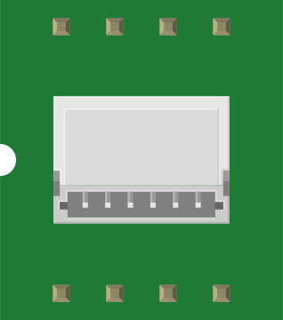
 Design with EM406 GPS Connector in Cirkit Designer
Introduction
The EM406 GPS Connector is a compact GPS receiver module designed to provide accurate positioning data. It features a built-in antenna and low power consumption, making it ideal for a wide range of applications. Its small form factor and ease of integration make it a popular choice for hobbyists and professionals alike.
Explore Projects Built with EM406 GPS Connector
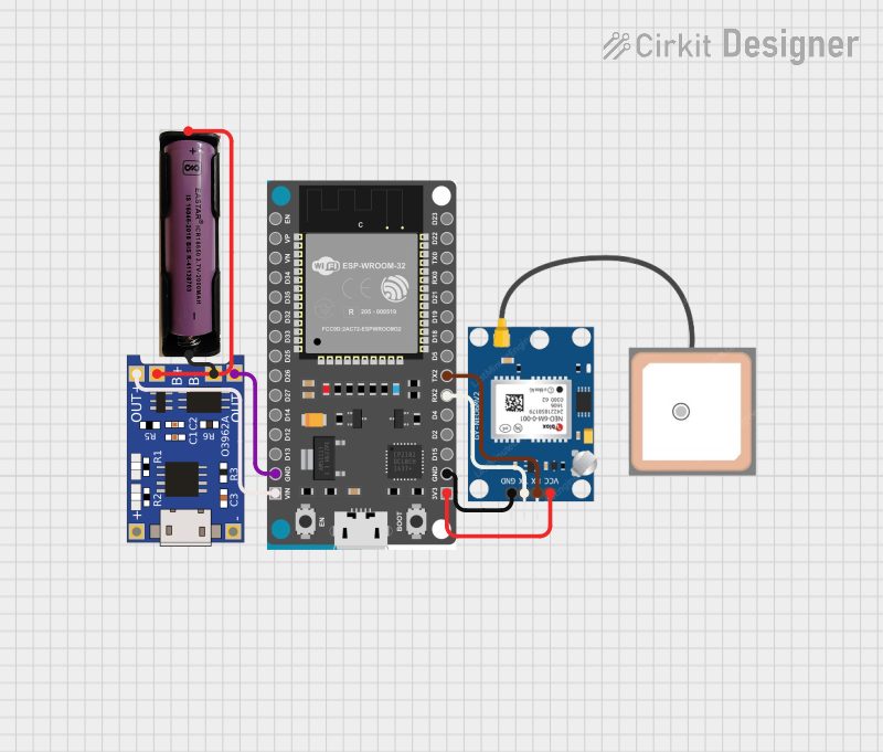 Open Project in Cirkit Designer
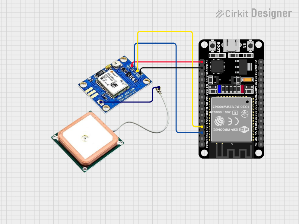 Open Project in Cirkit Designer
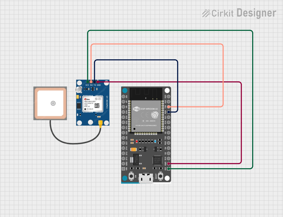 Open Project in Cirkit Designer
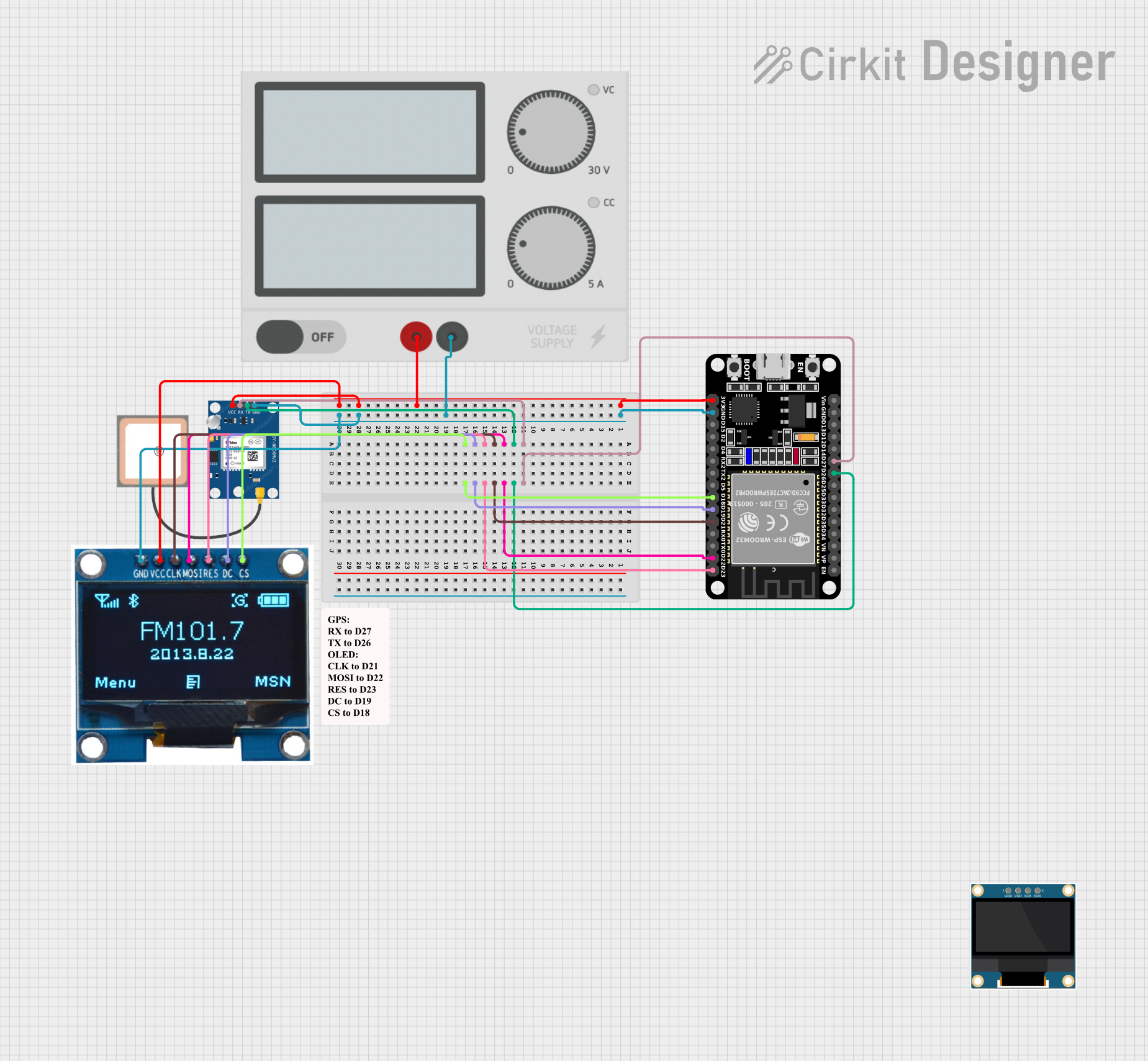 Open Project in Cirkit Designer
Explore Projects Built with EM406 GPS Connector
Open Project in Cirkit DesignerOpen Project in Cirkit DesignerOpen Project in Cirkit DesignerOpen Project in Cirkit DesignerCommon Applications and Use Cases
- GPS tracking systems
- Navigation devices
- Robotics and drones
- IoT (Internet of Things) projects
- Time synchronization for embedded systems
Technical Specifications
The EM406 GPS Connector is equipped with advanced features to ensure reliable performance in various environments. Below are its key technical details:
Key Technical Details
- Input Voltage: 3.3V to 5.0V DC
- Current Consumption: 44mA (typical)
- Communication Protocol: NMEA 0183 (default baud rate: 4800 bps)
- Position Accuracy: < 10 meters (CEP)
- Update Rate: 1 Hz (default)
- Operating Temperature: -40°C to +85°C
- Built-in Antenna: Yes (patch antenna)
- Dimensions: 30mm x 30mm x 10mm
Pin Configuration and Descriptions
The EM406 GPS Connector has a 6-pin interface for communication and power. Below is the pinout and description:
| Pin | Name | Description |
|---|---|---|
| 1 | VCC | Power supply input (3.3V to 5.0V DC) |
| 2 | GND | Ground connection |
| 3 | TX | Transmit data (serial output, NMEA sentences) |
| 4 | RX | Receive data (serial input, for configuration) |
| 5 | PPS | Pulse per second output (for precise timing) |
| 6 | NC | Not connected (reserved for future use) |
Usage Instructions
The EM406 GPS Connector is straightforward to use in electronic projects. Below are the steps and best practices for integrating it into your circuit.
How to Use the EM406 GPS Connector
- Power the Module: Connect the VCC pin to a 3.3V or 5.0V DC power source and the GND pin to ground.
- Connect to a Microcontroller: Use the TX pin to send GPS data to your microcontroller. Optionally, connect the RX pin if you need to send configuration commands to the module.
- Read GPS Data: The module outputs NMEA sentences (e.g., GPGGA, GPRMC) via the TX pin. These sentences contain information such as latitude, longitude, altitude, and time.
- Optional PPS Signal: Use the PPS pin for applications requiring precise timing.
Important Considerations and Best Practices
- Ensure the module has a clear view of the sky for optimal GPS signal reception.
- Avoid placing the module near sources of electromagnetic interference (e.g., motors, Wi-Fi modules).
- Use a level shifter if interfacing the module with a 3.3V microcontroller while powering it with 5.0V.
- The default baud rate is 4800 bps. Configure your microcontroller's UART accordingly.
Example: Connecting to an Arduino UNO
Below is an example of how to connect and use the EM406 GPS Connector with an Arduino UNO:
Wiring
- VCC: Connect to the Arduino's 5V pin.
- GND: Connect to the Arduino's GND pin.
- TX: Connect to the Arduino's RX pin (pin 0).
- RX: Connect to the Arduino's TX pin (pin 1).
Code Example
#include <SoftwareSerial.h>

// Define RX and TX pins for the GPS module
SoftwareSerial gpsSerial(4, 3); // RX = pin 4, TX = pin 3

void setup() {
  Serial.begin(9600); // Initialize Serial Monitor
  gpsSerial.begin(4800); // Initialize GPS module communication

  Serial.println("EM406 GPS Connector Test");
}

void loop() {
  while (gpsSerial.available()) {
    char c = gpsSerial.read(); // Read data from GPS module
    Serial.print(c); // Output GPS data to Serial Monitor

    // NMEA sentences will be displayed in the Serial Monitor
    // Example: $GPGGA,123456.00,3723.2475,N,12158.3416,W,1,08,0.9,545.4,M,46.9,M,,*47
  }
}
Notes
- Use the
SoftwareSeriallibrary to avoid conflicts with the Arduino's hardware serial pins. - Ensure the GPS module is powered and has a clear view of the sky before running the code.
Troubleshooting and FAQs
Common Issues and Solutions
No GPS Data Output
- Cause: The module may not have a clear view of the sky.
- Solution: Move the module to an open area with minimal obstructions.
Garbage Data in Serial Monitor
- Cause: Incorrect baud rate configuration.
- Solution: Ensure the baud rate in your code matches the module's default (4800 bps).
No Fix or Inaccurate Positioning
- Cause: Weak GPS signal or interference.
- Solution: Ensure the module is not near sources of interference and has a clear view of the sky.
Module Not Powering On
- Cause: Incorrect power supply voltage.
- Solution: Verify that the VCC pin is receiving 3.3V to 5.0V DC.
FAQs
Q: Can I change the baud rate of the EM406 GPS Connector?
A: Yes, the baud rate can be changed by sending specific configuration commands via the RX pin.Q: Does the module work indoors?
A: The module may work indoors near windows, but performance is significantly better outdoors.Q: What is the purpose of the PPS pin?
A: The PPS (Pulse Per Second) pin provides a precise timing signal, useful for time synchronization applications.Q: Can I use the module with a 3.3V microcontroller?
A: Yes, the module is compatible with 3.3V systems. Ensure proper voltage levels for communication.
This concludes the documentation for the EM406 GPS Connector.