How to Use open-smart_max7219: Examples, Pinouts, and Specs
Introduction
The Open-Smart MAX7219 is a compact, serial input/output common-cathode display driver designed to control up to 64 individual LEDs or 8 seven-segment displays. It simplifies the process of driving multiple LEDs by requiring only a single microcontroller pin for data transmission. This makes it an ideal choice for projects involving LED matrices, numeric displays, or other multi-LED configurations.
Explore Projects Built with open-smart_max7219


Explore Projects Built with open-smart_max7219
Common Applications and Use Cases
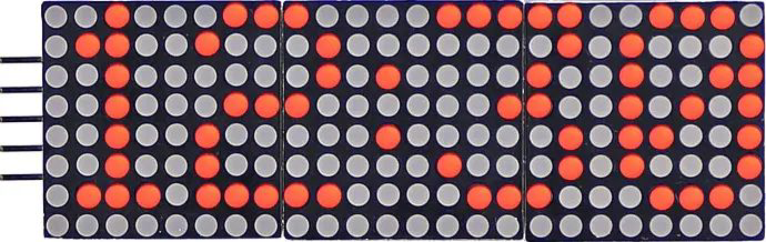
- Driving 8x8 LED matrices for text or graphics display
- Controlling up to 8 seven-segment numeric displays
- Creating digital clocks, counters, or scoreboards
- LED-based visual indicators or animations
- Simplifying LED control in microcontroller-based projects
Technical Specifications
The MAX7219 is a versatile and efficient display driver with the following key specifications:
| Parameter | Value |
|---|---|
| Operating Voltage | 4.0V to 5.5V |
| Maximum Current | 330mA (typical, depending on load) |
| Communication Interface | Serial (SPI-compatible) |
| Number of Controlled LEDs | Up to 64 individual LEDs or 8 digits |
| LED Drive Type | Common-cathode |
| Maximum Clock Frequency | 10 MHz |
| Operating Temperature | -40°C to +85°C |
Pin Configuration and Descriptions
The MAX7219 module typically has a 5-pin interface for communication and power. Below is the pinout:
| Pin | Name | Description |
|---|---|---|
| 1 | VCC | Power supply input (4.0V to 5.5V) |
| 2 | GND | Ground connection |
| 3 | DIN | Serial data input (connects to microcontroller's MOSI pin) |
| 4 | CS | Chip select (active low, used to enable communication with the MAX7219) |
| 5 | CLK | Serial clock input (connects to microcontroller's SCK pin) |
Usage Instructions
How to Use the MAX7219 in a Circuit
- Power the Module: Connect the VCC pin to a 5V power source and the GND pin to ground.
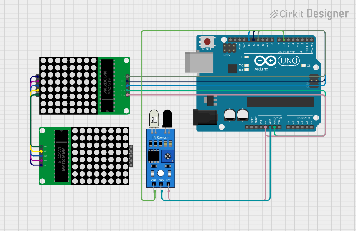
- Connect to Microcontroller:
- Connect the
DINpin to the microcontroller's MOSI (Master Out Slave In) pin. - Connect the
CLKpin to the microcontroller's SCK (Serial Clock) pin. - Connect the
CSpin to a digital output pin on the microcontroller.
- Connect the
- Load the Required Library: If using an Arduino, install the
LedControllibrary, which simplifies communication with the MAX7219. - Write Code: Use the library functions to initialize the module, set brightness, and control the LEDs or displays.
Important Considerations and Best Practices
- Current Limiting: The MAX7219 includes internal current limiting, so external resistors are not required for the LEDs.
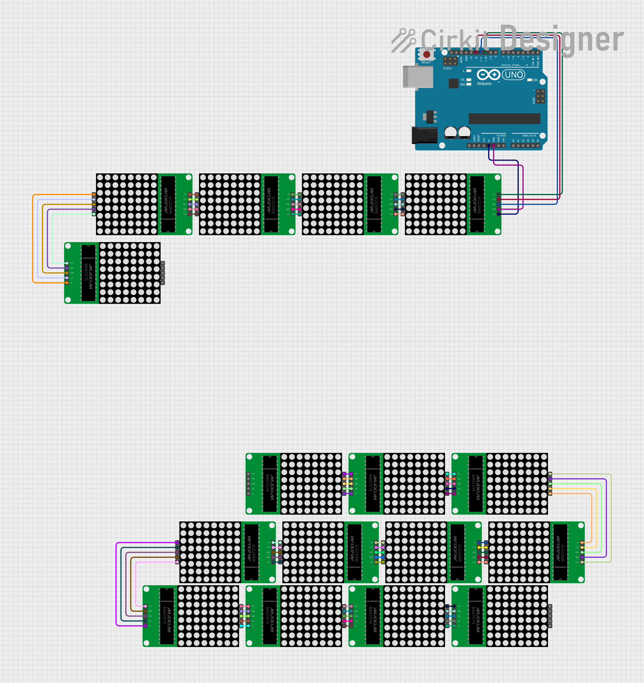
- Daisy-Chaining: Multiple MAX7219 modules can be daisy-chained to control more LEDs or displays. Connect the
DOUTpin of one module to theDINpin of the next. - Decoupling Capacitor: Place a 10µF capacitor across the VCC and GND pins to stabilize the power supply.
- Brightness Control: Use the intensity register to adjust the brightness of the LEDs.
Example Code for Arduino UNO
Below is an example of how to use the MAX7219 with an Arduino UNO to control an 8x8 LED matrix:
#include <LedControl.h> // Include the LedControl library

// Initialize the LedControl object
// Parameters: DIN pin, CLK pin, CS pin, number of devices
LedControl lc = LedControl(12, 11, 10, 1);

void setup() {
  // Wake up the MAX7219 from power-saving mode
  lc.shutdown(0, false);

  // Set the brightness level (0 = dim, 15 = brightest)
  lc.setIntensity(0, 8);

  // Clear the display
  lc.clearDisplay(0);

  // Display a pattern on the 8x8 LED matrix
  for (int row = 0; row < 8; row++) {
    lc.setRow(0, row, 0b10101010); // Alternating pattern for each row
  }
}

void loop() {
  // No actions in the loop for this example
}
Notes on the Code
- Replace
12,11, and10with the actual pins connected toDIN,CLK, andCSrespectively. - The
setRow()function is used to control individual rows of the LED matrix. Each row is represented by an 8-bit binary value.
Troubleshooting and FAQs
Common Issues and Solutions
No Display Output:
- Ensure the power supply is stable and within the operating voltage range (4.0V to 5.5V).
- Verify all connections, especially
DIN,CLK, andCS. - Check that the
LedControllibrary is correctly installed and included in your code.
Flickering LEDs:
- Add a decoupling capacitor (10µF) across the VCC and GND pins to stabilize the power supply.
- Ensure the microcontroller's SPI clock speed is not too high (below 10 MHz).
Incorrect LED Patterns:
- Verify the data being sent to the MAX7219. Use the
setRow()orsetColumn()functions correctly. - Check for loose or incorrect wiring.
- Verify the data being sent to the MAX7219. Use the
Brightness Issues:
- Adjust the intensity register using the
setIntensity()function in the code. - Ensure the power supply can handle the current requirements of the LEDs.
- Adjust the intensity register using the
FAQs
Q: Can I use the MAX7219 with a 3.3V microcontroller?
A: The MAX7219 requires a minimum operating voltage of 4.0V. If using a 3.3V microcontroller, level shifters are needed for proper communication.
Q: How many MAX7219 modules can I daisy-chain?
A: Theoretically, you can daisy-chain up to 8 modules, but the actual number depends on the power supply and signal integrity.
Q: Can I control individual LEDs in an 8x8 matrix?
A: Yes, you can control individual LEDs by addressing their row and column using the setRow() or setColumn() functions.
Q: Is the MAX7219 compatible with other display types?
A: The MAX7219 is designed for common-cathode displays, including 7-segment displays and LED matrices. It is not compatible with common-anode displays.