
How to Use Jtron 1-Channel Optoisolated Relay ModuleJtron / Generic: Examples, Pinouts, and Specs
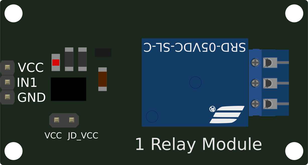
 Design with Jtron 1-Channel Optoisolated Relay ModuleJtron / Generic in Cirkit Designer
Introduction
The Jtron 1-Channel Optoisolated Relay Module is a versatile electronic component designed to control high-voltage devices using low-voltage signals. It features optoisolation, which ensures electrical isolation between the control circuit and the high-voltage load, protecting sensitive components from voltage spikes and interference. This module is widely used in home automation, industrial control systems, and DIY electronics projects.
Explore Projects Built with Jtron 1-Channel Optoisolated Relay ModuleJtron / Generic
 Open Project in Cirkit Designer
 Open Project in Cirkit Designer
 Open Project in Cirkit Designer
 Open Project in Cirkit Designer
Explore Projects Built with Jtron 1-Channel Optoisolated Relay ModuleJtron / Generic
Open Project in Cirkit DesignerOpen Project in Cirkit DesignerOpen Project in Cirkit DesignerOpen Project in Cirkit DesignerCommon Applications
- Home automation (e.g., controlling lights, fans, or appliances)
- Industrial equipment control
- Robotics and IoT projects
- Motor and pump control
- Signal isolation in sensitive circuits
Technical Specifications
Below are the key technical details of the Jtron 1-Channel Optoisolated Relay Module:
| Parameter | Specification |
|---|---|
| Operating Voltage | 5V DC |
| Trigger Voltage | 3.3V to 5V DC |
| Relay Type | SPDT (Single Pole Double Throw) |
| Maximum Load Voltage | 250V AC / 30V DC |
| Maximum Load Current | 10A |
| Optoisolation | Yes |
| Dimensions | 50mm x 26mm x 18.5mm |
| Mounting Holes | 2 x M3 holes for secure mounting |
Pin Configuration
The module has a total of 6 pins and terminals, as described below:
Control Side (Low Voltage)
| Pin | Name | Description |
|---|---|---|
| 1 | VCC | Connect to 5V DC power supply |
| 2 | GND | Connect to ground of the power supply |
| 3 | IN | Control signal input (3.3V to 5V logic level) |
Load Side (High Voltage)
| Terminal | Name | Description |
|---|---|---|
| 1 | COM | Common terminal for the relay switch |
| 2 | NO | Normally Open terminal (connected when relay is active) |
| 3 | NC | Normally Closed terminal (connected when relay is inactive) |
Usage Instructions
How to Use the Module in a Circuit
- Power the Module: Connect the VCC pin to a 5V DC power supply and the GND pin to the ground of the same power supply.
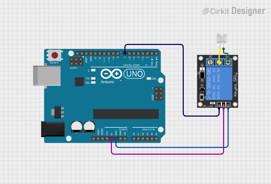
- Control Signal: Connect the IN pin to a digital output pin of a microcontroller (e.g., Arduino UNO). The relay will activate when the control signal is HIGH (logic 1).
- Connect the Load:
- Connect the high-voltage device to the COM terminal.
- Use the NO terminal if you want the device to turn on when the relay is active.
- Use the NC terminal if you want the device to turn off when the relay is active.
- Isolation: Ensure that the low-voltage control circuit and high-voltage load circuit are electrically isolated.
Important Considerations
- Power Supply: Ensure the module is powered with a stable 5V DC supply.
- Load Ratings: Do not exceed the maximum load voltage (250V AC / 30V DC) or current (10A).
- Safety: Always handle high-voltage connections with care. Disconnect power before making changes to the circuit.
- Optoisolation: The optoisolator protects the control circuit, but proper grounding and wiring practices are essential for safety.
Example: Using with Arduino UNO
Below is an example of how to control the relay module using an Arduino UNO:
// Example: Controlling Jtron 1-Channel Relay Module with Arduino UNO

// Define the pin connected to the relay module's IN pin
const int relayPin = 7;

void setup() {
  // Set the relay pin as an output
  pinMode(relayPin, OUTPUT);

  // Ensure the relay is off at startup
  digitalWrite(relayPin, LOW);
}

void loop() {
  // Turn the relay ON (activates the connected device)
  digitalWrite(relayPin, HIGH);
  delay(5000); // Keep the relay on for 5 seconds

  // Turn the relay OFF (deactivates the connected device)
  digitalWrite(relayPin, LOW);
  delay(5000); // Keep the relay off for 5 seconds
}
Notes:
- Replace
relayPinwith the actual pin number connected to the IN pin of the relay module. - Ensure the Arduino and relay module share a common ground.
Troubleshooting and FAQs
Common Issues and Solutions
Relay Not Activating:
- Check if the VCC and GND pins are properly connected to a 5V DC power supply.
- Verify that the control signal (IN pin) is receiving a HIGH (3.3V to 5V) signal.
- Ensure the load connected to the relay does not exceed the rated voltage or current.
High Voltage Device Not Turning On/Off:
- Double-check the wiring of the COM, NO, and NC terminals.
- Ensure the high-voltage device is functional and properly connected.
Interference or Noise in the Circuit:
- Use a flyback diode across the relay coil to suppress voltage spikes.
- Keep high-voltage and low-voltage wiring separate to reduce interference.
Arduino Resets When Relay Activates:
- This may be caused by a power supply issue. Ensure the Arduino and relay module have sufficient and stable power.
FAQs
Q: Can I use this module with a 3.3V microcontroller?
A: Yes, the module can be triggered with a 3.3V control signal, but ensure the VCC pin is powered with 5V DC.
Q: Is the relay module suitable for DC loads?
A: Yes, the relay can handle DC loads up to 30V and 10A.
Q: Can I control multiple relays with one Arduino?
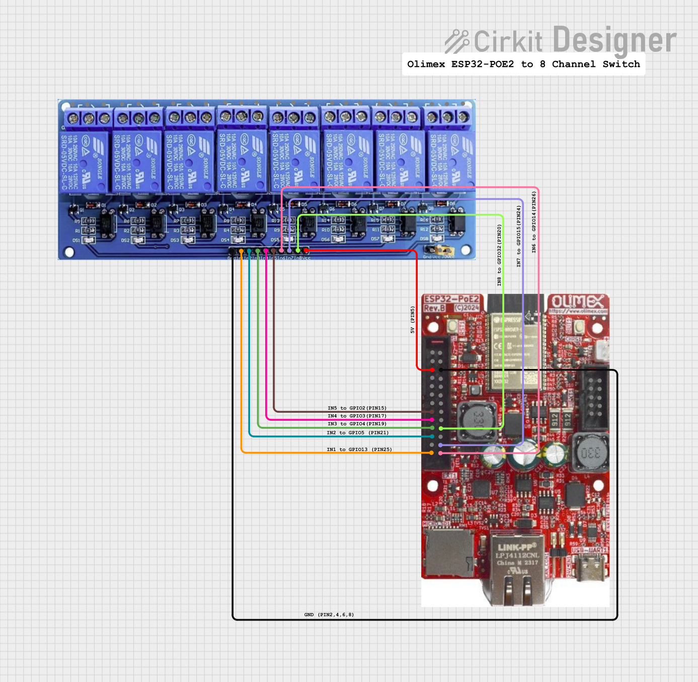
A: Yes, you can control multiple relay modules by connecting each IN pin to a separate digital output pin on the Arduino.
Q: Does the module require an external flyback diode?
A: The module typically includes a built-in flyback diode, but you can add an external one for additional protection if needed.
By following this documentation, you can safely and effectively use the Jtron 1-Channel Optoisolated Relay Module in your projects.