Cirkit Designer Logo
Cirkit Designer
Your all-in-one circuit design IDE
Home / 
Component Documentation

How to Use ESP32 with SIMCOM A7672s: Examples, Pinouts, and Specs

Image of ESP32 with SIMCOM A7672s
Cirkit Designer LogoDesign with ESP32 with SIMCOM A7672s in Cirkit Designer

Introduction

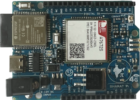
The ESP32 with SIMCOM A7672s Development Board by Bharat Pi is a powerful and versatile platform designed for IoT applications. It combines the capabilities of the ESP32 microcontroller with the SIMCOM A7672s module to provide both Wi-Fi and cellular communication options. This board is ideal for projects that require remote data collection, home automation, industrial control, and other IoT solutions where wireless connectivity is essential.

Explore Projects Built with ESP32 with SIMCOM A7672s

Use Cirkit Designer to design, explore, and prototype these projects online. Some projects support real-time simulation. Click "Open Project" to start designing instantly!
ESP32 with SIMCOM A7672s IoT Sensor Data Logger
Image of LM393 to LilygoSIM7000: A project utilizing ESP32 with SIMCOM A7672s in a practical application
This circuit integrates an ESP32 with SIMCOM A7672s module with an LM393 comparator for sensor data acquisition. The ESP32 is programmed to read a digital signal from the LM393's D0 output, corresponding to a threshold detection, and then sends this data to the Blynk Cloud using the SIMCOM A7672s module for remote monitoring. The LM393 is powered by the ESP32's 3.3V supply, and both share a common ground.
Cirkit Designer LogoOpen Project in Cirkit Designer
ESP32-Based Cellular and GPS Tracking System with User Interface
Image of Keychain Device: A project utilizing ESP32 with SIMCOM A7672s in a practical application
This circuit features an ESP32 microcontroller interfaced with a SIM 800L GSM module for cellular communication and a Neo 6M GPS module for location tracking. A voltage regulator is used to maintain a stable voltage supply from a polymer lithium-ion battery to the GSM, GPS, and ESP32 modules. Additionally, the circuit includes a pushbutton to trigger inputs and an LED with a current-limiting resistor, likely for status indication.
Cirkit Designer LogoOpen Project in Cirkit Designer
ESP8266 and SIM800L Based GPS Tracker with I2C LCD Display and Battery Power
Image of Little Innovator Competition: A project utilizing ESP32 with SIMCOM A7672s in a practical application
This circuit integrates an ESP8266 NodeMCU microcontroller with a SIM800L GSM module, a GPS NEO 6M module, and a 16x2 I2C LCD display for communication and location tracking. It also includes a pushbutton for user input, a piezo buzzer for audio alerts, and is powered by a 2x 18650 battery pack through an LM2596 step-down module.
Cirkit Designer LogoOpen Project in Cirkit Designer
ESP32-Controlled Multi-Color LED Array with GSM and GPS Functionality
Image of smart helmet: A project utilizing ESP32 with SIMCOM A7672s in a practical application
This circuit features an ESP32 microcontroller connected to multiple LEDs, a SIM800c GSM module with a speaker and microphone for audio input/output, and a GPS NEO 6M module for location tracking. The ESP32 controls the LEDs and communicates with the GSM and GPS modules via serial connections. Power management is handled by a TP4056 charging module connected to a 18650 Li-ion battery, with a rocker switch to control power flow.
Cirkit Designer LogoOpen Project in Cirkit Designer

Explore Projects Built with ESP32 with SIMCOM A7672s

Use Cirkit Designer to design, explore, and prototype these projects online. Some projects support real-time simulation. Click "Open Project" to start designing instantly!
Image of LM393 to LilygoSIM7000: A project utilizing ESP32 with SIMCOM A7672s in a practical application
ESP32 with SIMCOM A7672s IoT Sensor Data Logger
This circuit integrates an ESP32 with SIMCOM A7672s module with an LM393 comparator for sensor data acquisition. The ESP32 is programmed to read a digital signal from the LM393's D0 output, corresponding to a threshold detection, and then sends this data to the Blynk Cloud using the SIMCOM A7672s module for remote monitoring. The LM393 is powered by the ESP32's 3.3V supply, and both share a common ground.
Cirkit Designer LogoOpen Project in Cirkit Designer
Image of Keychain Device: A project utilizing ESP32 with SIMCOM A7672s in a practical application
ESP32-Based Cellular and GPS Tracking System with User Interface
This circuit features an ESP32 microcontroller interfaced with a SIM 800L GSM module for cellular communication and a Neo 6M GPS module for location tracking. A voltage regulator is used to maintain a stable voltage supply from a polymer lithium-ion battery to the GSM, GPS, and ESP32 modules. Additionally, the circuit includes a pushbutton to trigger inputs and an LED with a current-limiting resistor, likely for status indication.
Cirkit Designer LogoOpen Project in Cirkit Designer
Image of Little Innovator Competition: A project utilizing ESP32 with SIMCOM A7672s in a practical application
ESP8266 and SIM800L Based GPS Tracker with I2C LCD Display and Battery Power
This circuit integrates an ESP8266 NodeMCU microcontroller with a SIM800L GSM module, a GPS NEO 6M module, and a 16x2 I2C LCD display for communication and location tracking. It also includes a pushbutton for user input, a piezo buzzer for audio alerts, and is powered by a 2x 18650 battery pack through an LM2596 step-down module.
Cirkit Designer LogoOpen Project in Cirkit Designer
Image of smart helmet: A project utilizing ESP32 with SIMCOM A7672s in a practical application
ESP32-Controlled Multi-Color LED Array with GSM and GPS Functionality
This circuit features an ESP32 microcontroller connected to multiple LEDs, a SIM800c GSM module with a speaker and microphone for audio input/output, and a GPS NEO 6M module for location tracking. The ESP32 controls the LEDs and communicates with the GSM and GPS modules via serial connections. Power management is handled by a TP4056 charging module connected to a 18650 Li-ion battery, with a rocker switch to control power flow.
Cirkit Designer LogoOpen Project in Cirkit Designer

Common Applications and Use Cases

  • Remote monitoring and control systems
  • IoT-enabled smart devices
  • Asset tracking and logistics
  • Environmental monitoring
  • Agricultural technology solutions
  • Smart city infrastructure

Technical Specifications

Key Technical Details

  • Microcontroller: ESP32
  • Cellular Module: SIMCOM A7672s
  • Operating Voltage: 3.3V
  • Input Voltage: 5V via micro USB or Vin pin
  • Digital I/O Pins: 22
  • Analog Input Pins: 6 (ADC channels)
  • Flash Memory: 4MB
  • SRAM: 520KB
  • Wi-Fi: 802.11 b/g/n
  • Bluetooth: v4.2 BR/EDR and BLE
  • Cellular Network Support: LTE Cat 4, GSM/GPRS
  • Frequency Bands: LTE FDD, LTE TDD, GSM/GPRS/EDGE
  • GPS: Integrated GNSS (GPS, GLONASS, BeiDou/Compass, Galileo, QZSS)

Pin Configuration and Descriptions

Pin Number Function Description
1 GND Ground
2 3V3 3.3V power supply
3 EN Reset pin (active low)
4 IO23 General purpose I/O, SPI MOSI
5 IO22 General purpose I/O, SPI SCK
6 TXD0 UART0 transmit
7 RXD0 UART0 receive
... ... ...
N SIM_TXD SIMCOM A7672s UART transmit
N+1 SIM_RXD SIMCOM A7672s UART receive

Note: This is a simplified representation of the pin configuration. Refer to the full datasheet for comprehensive details.

Usage Instructions

How to Use the Component in a Circuit

  1. Power Supply: Ensure that the board is powered through the micro USB port or Vin pin with a stable 5V supply.
  2. Antenna Connections: Attach the appropriate antennas to the ESP32 and SIMCOM A7672s modules for Wi-Fi and cellular connectivity.
  3. Programming: Use the USB interface to program the ESP32 with the desired firmware. The SIMCOM A7672s can be controlled via AT commands sent from the ESP32 over the UART interface.
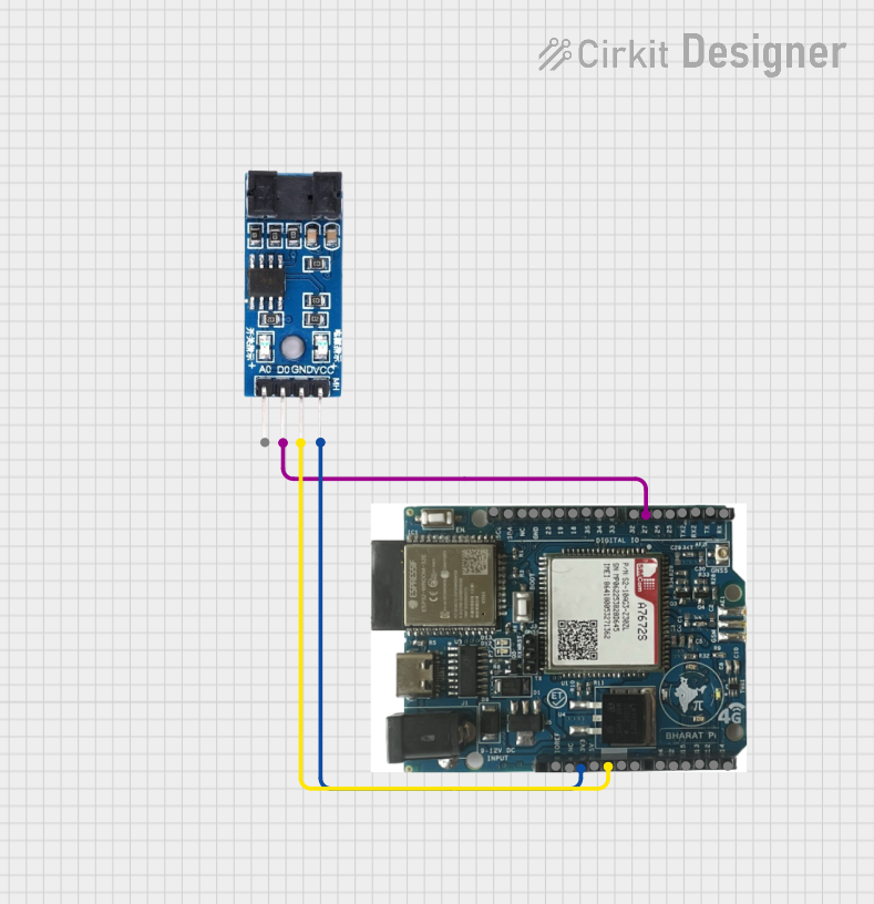
  4. I/O Connections: Connect sensors, actuators, or other peripherals to the available I/O pins, taking care to match the voltage levels and current capabilities.

Important Considerations and Best Practices

  • Always disconnect the power source before making or altering connections.
  • Use proper ESD precautions when handling the board to prevent damage to sensitive components.
  • Ensure that the antenna used for the cellular module is rated for the correct frequency bands.
  • When designing the enclosure, consider proper ventilation for heat dissipation.

Troubleshooting and FAQs

Common Issues Users Might Face

  • No Network Connection: Verify that the antennas are properly connected and that the SIM card is active and inserted correctly.
  • Failure to Boot: Check the power supply for proper voltage and current capabilities.
  • Programming Errors: Ensure that the correct drivers are installed and that the board is selected properly in the IDE.

Solutions and Tips for Troubleshooting

  • Power Issues: Use a multimeter to verify the input voltage and current.
  • Connectivity Issues: Test the SIM card in another device to confirm it is active.
  • Signal Strength: Place the device in an area with good signal reception or consider using an external antenna for improved performance.

Example Code for Arduino UNO

#include <HardwareSerial.h>

HardwareSerial SIMCOM(1); // Use hardware serial port 1 for SIMCOM A7672s

void setup() {
  // Start the hardware serial communication with the SIMCOM A7672s module
  SIMCOM.begin(115200, SERIAL_8N1, 16, 17); // RX, TX pins
  // Start the serial communication for debugging
  Serial.begin(115200);
  // Send AT command to check communication with SIMCOM A7672s module
  SIMCOM.println("AT");
}

void loop() {
  // Check if the module is responding to AT commands
  if (SIMCOM.available()) {
    String response = SIMCOM.readString();
    Serial.print("SIMCOM module response: ");
    Serial.println(response);
  }
  // Add a delay between AT commands to prevent spamming the module
  delay(1000);
}

Note: The above code is a simple example to test communication with the SIMCOM A7672s module. For specific applications, additional code will be required to handle cellular network connectivity and data transmission.

Remember to adjust the pin numbers in the SIMCOM.begin() function to match the actual RX and TX pins used for communication with the SIMCOM A7672s module on your development board.