How to Use ESP32 TTGO: Examples, Pinouts, and Specs
Introduction
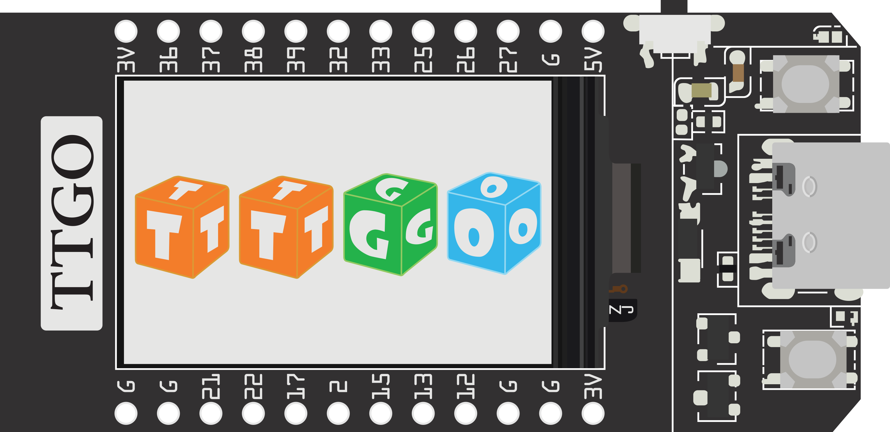
The ESP32 TTGO is a versatile and powerful development board that integrates an ESP32 module with WiFi and Bluetooth capabilities, along with a 3.2-inch color touchscreen display. This board is ideal for Internet of Things (IoT) projects, smart home applications, and any wireless-enabled device development. Its rich set of I/O pins and interfaces makes it suitable for a wide range of applications, from simple LED control to complex graphical user interfaces.
Explore Projects Built with ESP32 TTGO
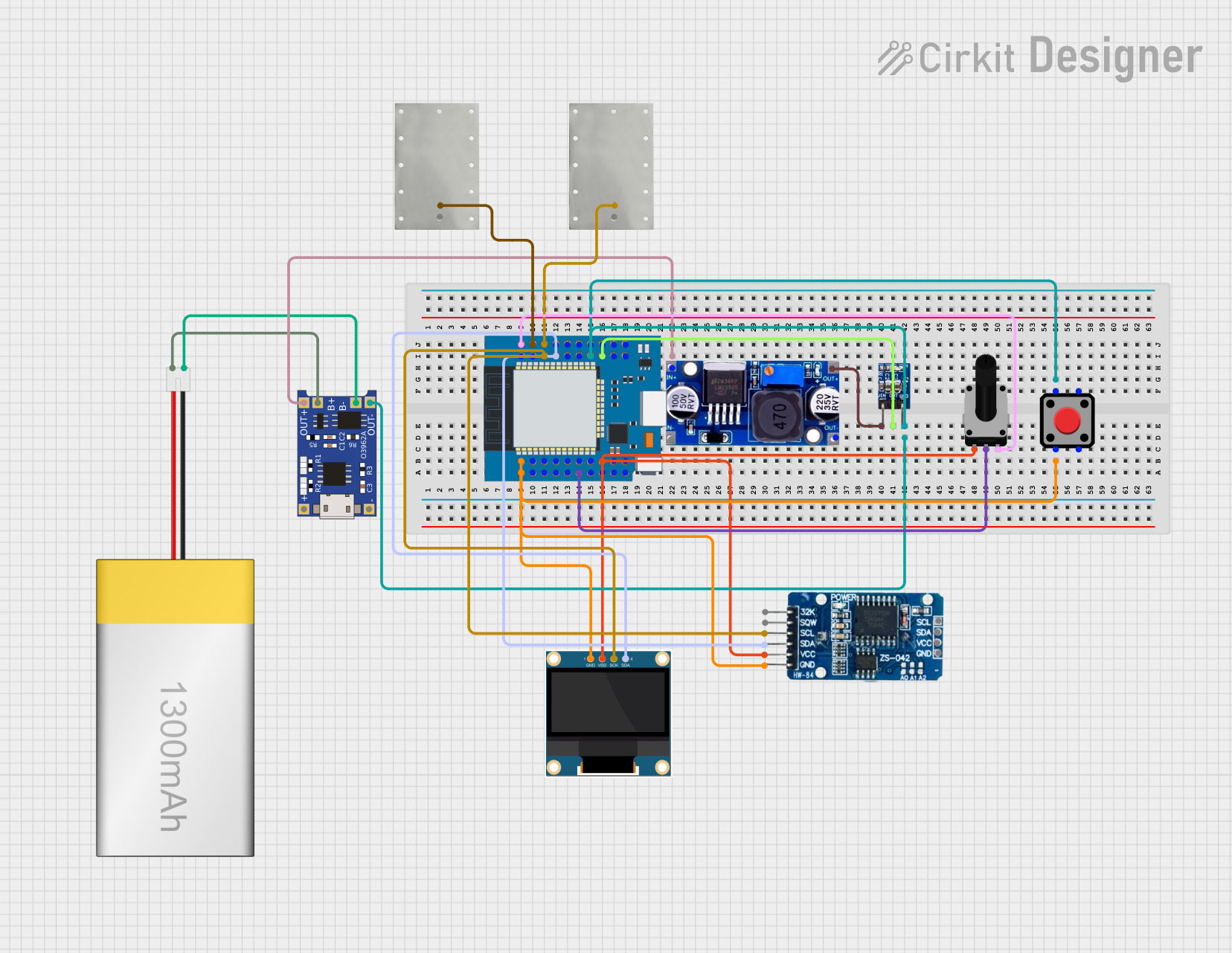
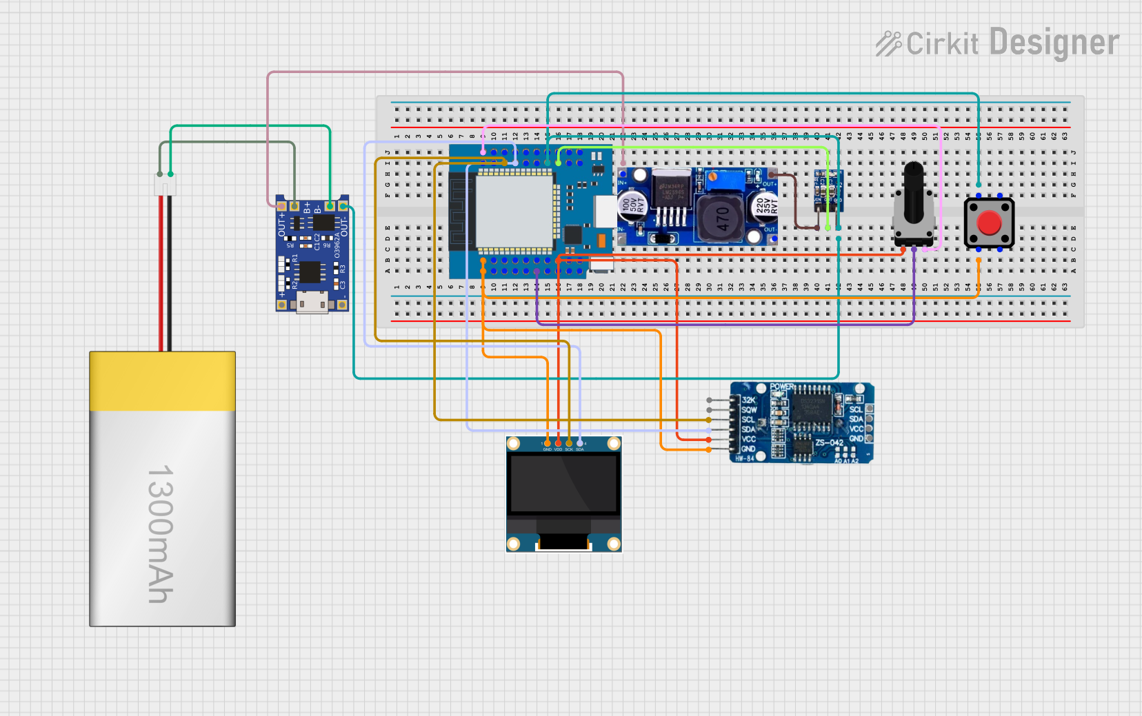
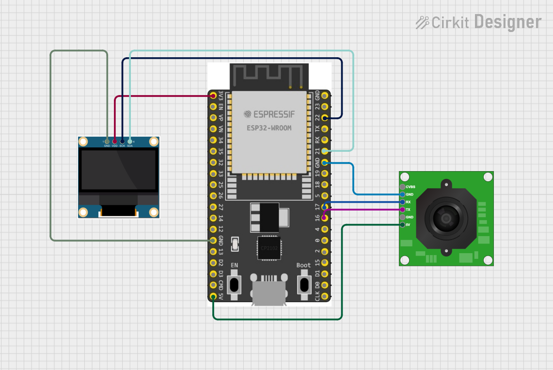

Explore Projects Built with ESP32 TTGO
Technical Specifications
General Features
- Microcontroller: ESP32
- Operating Voltage: 3.3V
- Input Voltage: 7-12V
- Digital I/O Pins: 38
- Analog Input Pins: 18
- Flash Memory: 4MB
- SRAM: 520 KB
- Clock Speed: 240 MHz
- Built-in WiFi: 802.11 b/g/n
- Built-in Bluetooth: v4.2 BR/EDR and BLE
- Display: 3.2-inch color touchscreen
Pin Configuration
| Pin Number | Function | Description |
|---|---|---|
| 1-38 | GPIO | General Purpose Input/Output pins |
| 39-56 | Analog Inputs | Analog to Digital Converter channels |
| GND | Ground | Common ground for power and logic |
| 3V3 | 3.3V Power | Regulated 3.3V power supply |
| VIN | Voltage Input | Unregulated input voltage for the board |
| TX0, RX0 | Serial UART | Serial communication pins |
| SCL, SDA | I2C | I2C communication pins |
| SCK, MISO, | SPI | SPI communication pins |
| MOSI, SS | ||
| EN | Enable | Chip enable, active high |
| IO0 | Boot | Boot mode selection, low for serial bootload |
Usage Instructions
Basic Setup
To get started with the ESP32 TTGO, you will need to:
- Connect the board to your computer using a micro USB cable.
- Install the necessary drivers for the USB-to-UART bridge chip.
- Install the ESP32 board support package in your Arduino IDE or preferred development environment.
- Select the correct board and port in your development environment.
Programming the Board
When programming the ESP32 TTGO, ensure that:
- The board is powered correctly, either through USB or an external power supply.
- The correct board configuration is selected in your development environment.
- You understand the pinout and functionality of the ESP32 to avoid damage.
Display Usage
To use the built-in touchscreen display, you will need to:
- Install the appropriate display library that supports the screen's controller.
- Initialize the display in your code and use the library's functions to draw graphics or text.
Connectivity
For WiFi and Bluetooth functionality:
- Use the
WiFi.handBluetoothSerial.hlibraries included with the ESP32 board package. - Follow the examples provided with the libraries to connect to a network or pair with other Bluetooth devices.
Best Practices
- Always disconnect the board from power when making changes to the circuit.
- Use a logic level converter if interfacing with 5V devices.
- Avoid drawing too much current from the I/O pins to prevent damage.
Example Code
Below is a simple example of how to connect the ESP32 TTGO to a WiFi network:
#include <WiFi.h>

// Replace with your network credentials
const char* ssid = "your_SSID";
const char* password = "your_PASSWORD";

void setup() {
  Serial.begin(115200);
  // Connect to Wi-Fi
  WiFi.begin(ssid, password);
  while (WiFi.status() != WL_CONNECTED) {
    delay(500);
    Serial.println("Connecting to WiFi...");
  }
  Serial.println("Connected to WiFi");
}

void loop() {
  // Your code here
}
Troubleshooting and FAQs
Common Issues
- Board not recognized: Ensure drivers are installed and the USB cable is functioning.
- Display not working: Verify the correct library is installed and pins are configured properly.
- WiFi/Bluetooth not connecting: Check your network credentials and device compatibility.
FAQs
Q: How do I reset the ESP32 TTGO? A: Press the EN button on the board to reset it.
Q: Can I use the ESP32 TTGO with a battery? A: Yes, you can power the board with a battery connected to the VIN pin, ensuring the voltage is within the specified range.
Q: What is the maximum current draw from an I/O pin? A: The maximum current per I/O pin is 12 mA.
For further assistance, consult the ESP32 TTGO community forums or the manufacturer's support resources.