How to Use Adafruit LIS3DH Triple-Axis Accelerometer: Examples, Pinouts, and Specs
Introduction
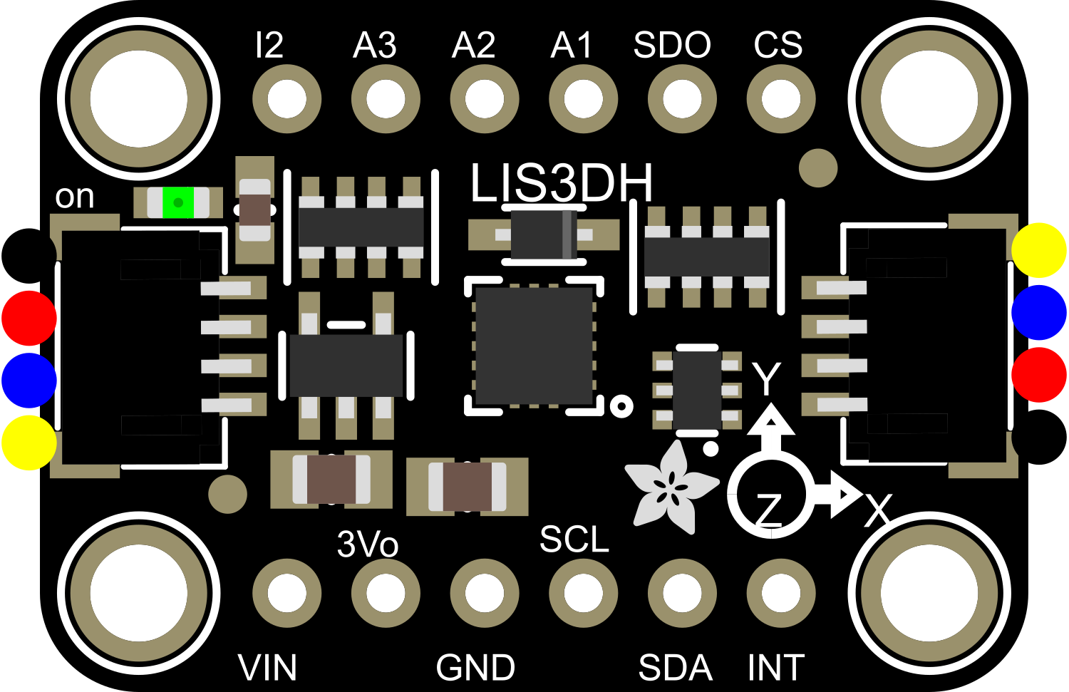
The Adafruit LIS3DH Triple-Axis Accelerometer is a versatile and high-precision sensor that measures acceleration along three axes: X, Y, and Z. This MEMS (micro-electromechanical systems) sensor provides digital output and can measure accelerations up to ±16g. It is widely used in various applications such as mobile devices, gaming controllers, vibration detection, and motion tracking.
Explore Projects Built with Adafruit LIS3DH Triple-Axis Accelerometer
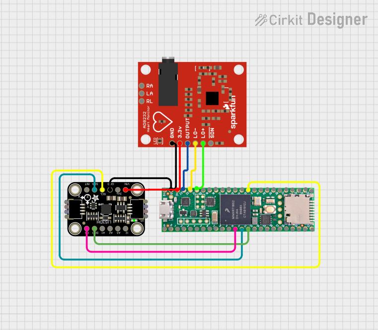
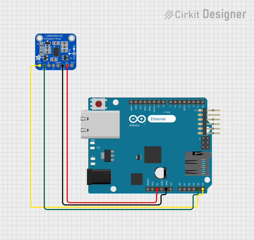

Explore Projects Built with Adafruit LIS3DH Triple-Axis Accelerometer
Technical Specifications
Key Features
- Model: Adafruit LIS3DH
- Voltage Supply: 1.9V to 3.6V
- Current Consumption: 2µA (low-power mode)
- Sensing Range: ±2g/±4g/±8g/±16g (selectable)
- Resolution: 10-bit (normal mode) or 12-bit (high-resolution mode)
- Output: I2C and SPI digital interfaces
- Operating Temperature: -40°C to +85°C
Pin Configuration and Descriptions
| Pin Number | Name | Description |
|---|---|---|
| 1 | SCL | Serial Clock for I2C communication |
| 2 | SDA | Serial Data for I2C communication |
| 3 | SA0 | I2C address selection pin |
| 4 | CS | Chip Select for SPI communication |
| 5 | SDO | Serial Data Out for SPI communication |
| 6 | GND | Ground connection |
| 7 | VDD | Power supply (1.9V to 3.6V) |
Usage Instructions
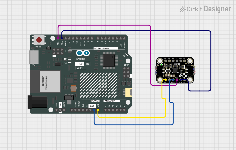
Integration with a Circuit
To use the Adafruit LIS3DH in a circuit, connect the VDD pin to a power supply within the specified voltage range and the GND pin to the common ground. For I2C communication, connect the SCL and SDA pins to the corresponding I2C clock and data lines on your microcontroller. If using SPI, connect the SDO, SCL (as SCK), and CS pins to your microcontroller's SPI interface.
Best Practices
- Use pull-up resistors on the I2C lines (SCL and SDA) if they are not already present on your microcontroller board.
- Keep the power supply stable and within the specified voltage range to ensure accurate measurements.
- Place the accelerometer as close as possible to the center of mass of the object you're measuring to get the most accurate readings.
- Avoid physical shocks and vibrations during operation that exceed the sensor's maximum rating.
Example Code for Arduino UNO
#include <Wire.h>
#include <Adafruit_LIS3DH.h>
#include <Adafruit_Sensor.h>

// Create an instance of the Adafruit_LIS3DH class
Adafruit_LIS3DH lis = Adafruit_LIS3DH();

void setup(void) {
  Serial.begin(9600);
  if (!lis.begin(0x18)) {   // Change to 0x19 for alternative I2C address
    Serial.println("Could not find a valid LIS3DH sensor, check wiring!");
    while (1);
  }

  // Set the measurement range
  lis.setRange(LIS3DH_RANGE_4_G);   // 2, 4, 8 or 16 G!

  Serial.println("LIS3DH found!");
}

void loop() {
  lis.read();      // Get new data from the sensor
  Serial.print("X: "); Serial.print(lis.x);
  Serial.print(" \tY: "); Serial.print(lis.y);
  Serial.print(" \tZ: "); Serial.println(lis.z);

  delay(200);     // Delay between readings
}
Troubleshooting and FAQs
Common Issues
- Sensor not detected: Ensure that the wiring is correct and that the correct I2C address is used in the code.
- Inaccurate readings: Verify that the sensor is properly calibrated and that the power supply is stable.
- Noisy data: Implement filtering algorithms or increase the data rate to smooth out the readings.
FAQs
Q: Can the LIS3DH operate on a 5V system? A: The LIS3DH is not 5V tolerant; however, you can use a logic level converter to interface with a 5V system.
Q: How do I change the I2C address? A: The I2C address can be changed by connecting the SA0 pin to either ground (0x18) or VDD (0x19).
Q: What is the maximum sampling rate of the LIS3DH? A: The LIS3DH can sample up to 5 kHz in the high-resolution mode.
Q: How do I calibrate the accelerometer? A: Calibration involves storing the offset values when the sensor is at rest and then subtracting these values from the readings during operation.
For further assistance, consult the Adafruit LIS3DH datasheet and the Adafruit Sensor library documentation.