How to Use Heltec ESP 32 Lora: Examples, Pinouts, and Specs
Introduction
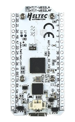
The Heltec ESP32 LoRa is a versatile microcontroller board developed by ESP, featuring the powerful ESP32 chip with integrated LoRa (Long Range) communication capabilities. This board is designed for IoT applications that require long-range wireless connectivity, low power consumption, and high performance. It is equipped with an OLED display, onboard Wi-Fi, and Bluetooth, making it a comprehensive solution for a wide range of projects.
Explore Projects Built with Heltec ESP 32 Lora

Explore Projects Built with Heltec ESP 32 Lora
Common Applications and Use Cases
- Internet of Things (IoT) devices and networks
- Remote environmental monitoring
- Smart agriculture and precision farming
- Asset tracking and geolocation
- Industrial automation and control systems
- Wireless sensor networks
Technical Specifications
Key Technical Details
| Parameter | Specification |
|---|---|
| Microcontroller | ESP32 dual-core processor |
| Wireless Connectivity | Wi-Fi 802.11 b/g/n, Bluetooth 4.2, LoRa |
| LoRa Frequency | 433 MHz / 868 MHz / 915 MHz (region-dependent) |
| Flash Memory | 4 MB (SPI Flash) |
| SRAM | 520 KB |
| Operating Voltage | 3.3V |
| Input Voltage Range | 5V (via USB) or 3.3V (via pin) |
| Power Consumption | Ultra-low power (varies based on usage) |
| OLED Display | 0.96-inch, 128x64 pixels, monochrome |
| GPIO Pins | 26 (multipurpose, including ADC, DAC, PWM, etc.) |
| Communication Interfaces | UART, SPI, I2C, I2S |
| Dimensions | 41 x 25 x 12 mm |
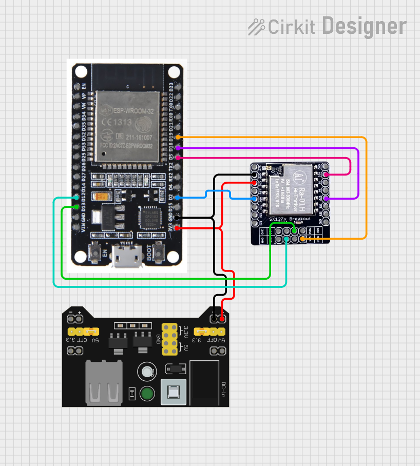
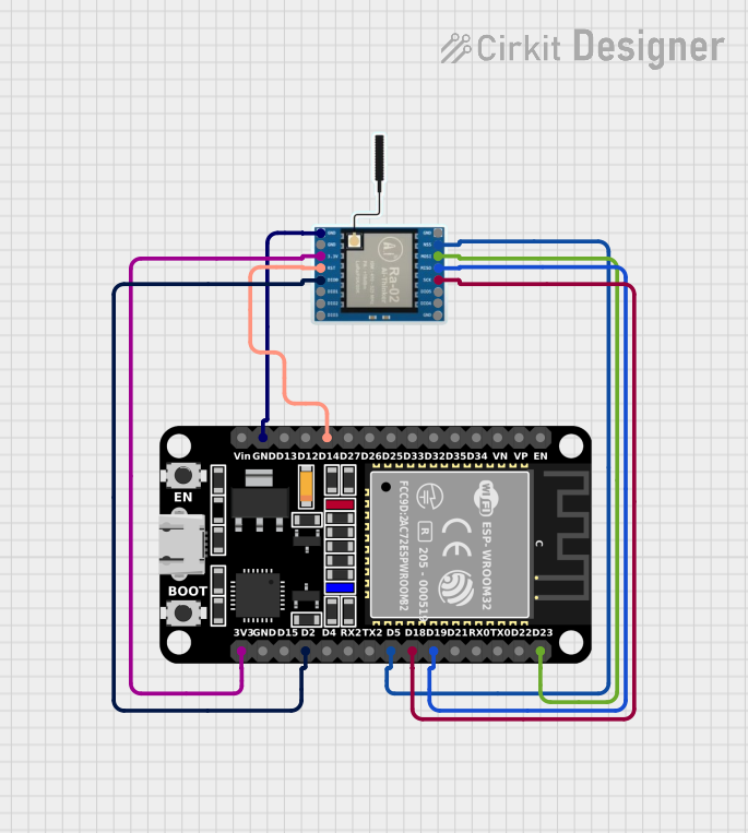
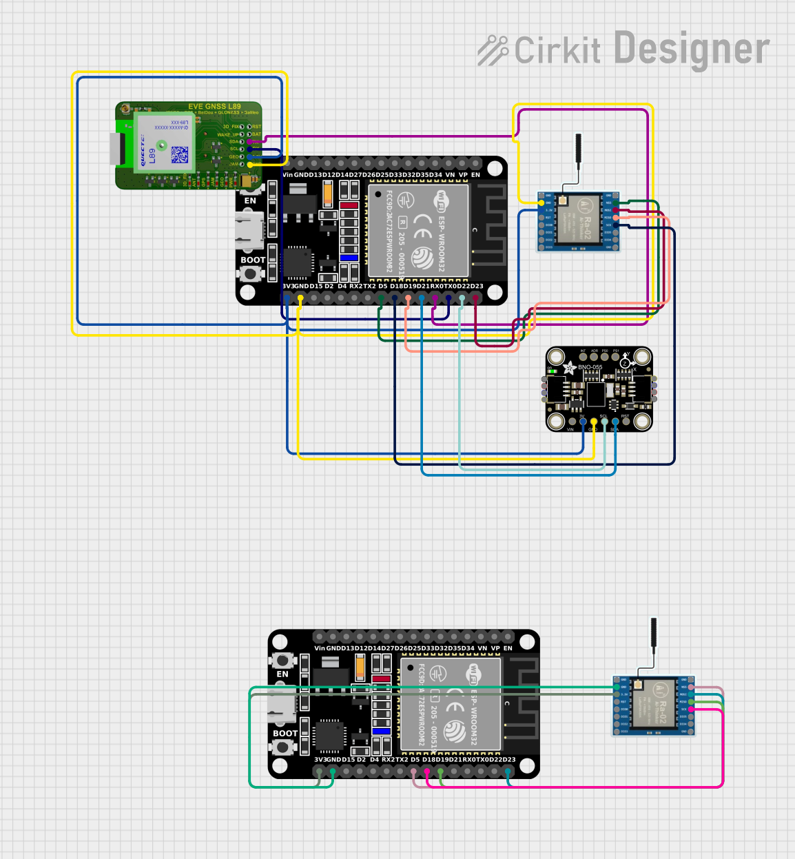
Pin Configuration and Descriptions
| Pin Name | Pin Number | Description |
|---|---|---|
| GND | Multiple | Ground pin |
| 3V3 | Multiple | 3.3V power output |
| VIN | - | Power input (5V via USB or external source) |
| GPIO0 | 0 | General-purpose I/O, boot mode selection |
| GPIO21 | 21 | I2C SDA (default) |
| GPIO22 | 22 | I2C SCL (default) |
| GPIO16 | 16 | LoRa Reset (connected to LoRa module) |
| GPIO17 | 17 | LoRa DIO1 (connected to LoRa module) |
| GPIO18 | 18 | SPI SCK (LoRa communication) |
| GPIO19 | 19 | SPI MISO (LoRa communication) |
| GPIO23 | 23 | SPI MOSI (LoRa communication) |
| GPIO25 | 25 | DAC1, PWM, or general-purpose I/O |
| GPIO26 | 26 | DAC2, PWM, or general-purpose I/O |
| GPIO27 | 27 | ADC, PWM, or general-purpose I/O |
Usage Instructions
How to Use the Component in a Circuit
Powering the Board:
- Connect the board to a 5V USB power source or supply 3.3V directly to the VIN pin.
- Ensure the power source can provide sufficient current (at least 500 mA).
Connecting Peripherals:
- Use the GPIO pins for connecting sensors, actuators, or other peripherals.
- For I2C devices, connect them to GPIO21 (SDA) and GPIO22 (SCL).
- For SPI communication, use GPIO18 (SCK), GPIO19 (MISO), and GPIO23 (MOSI).
Programming the Board:
- Install the Arduino IDE and add the ESP32 board support package.
- Select "Heltec ESP32 LoRa" as the board in the Arduino IDE.
- Connect the board to your computer via USB and upload your code.
Using LoRa Communication:
- Install the "LoRa" library in the Arduino IDE.
- Configure the LoRa frequency to match your region (e.g., 868 MHz for Europe).
Important Considerations and Best Practices
- Power Supply: Avoid supplying more than 3.3V to the GPIO pins to prevent damage.
- Antenna Connection: Always connect the LoRa antenna before powering the board to avoid damaging the LoRa module.
- Frequency Compliance: Ensure the LoRa frequency is compliant with local regulations.
- Heat Management: The ESP32 chip may heat up during operation; ensure proper ventilation.
Example Code for Arduino UNO
Below is an example of using the Heltec ESP32 LoRa to send a simple message via LoRa:
#include <SPI.h>
#include <LoRa.h> // Include the LoRa library

#define LORA_SCK 18  // SPI Clock pin
#define LORA_MISO 19 // SPI MISO pin
#define LORA_MOSI 23 // SPI MOSI pin
#define LORA_CS 5    // LoRa chip select pin
#define LORA_RST 14  // LoRa reset pin
#define LORA_IRQ 26  // LoRa IRQ pin

void setup() {
  Serial.begin(9600); // Initialize serial communication
  while (!Serial);

  Serial.println("Initializing LoRa...");

  // Initialize LoRa with frequency 868 MHz
  if (!LoRa.begin(868E6)) {
    Serial.println("LoRa initialization failed!");
    while (1);
  }

  Serial.println("LoRa initialized successfully!");
}

void loop() {
  Serial.println("Sending message...");
  LoRa.beginPacket(); // Start a new LoRa packet
  LoRa.print("Hello, LoRa!"); // Add message to the packet
  LoRa.endPacket(); // Send the packet

  delay(5000); // Wait 5 seconds before sending the next message
}
Troubleshooting and FAQs
Common Issues and Solutions
LoRa Initialization Fails:
- Ensure the LoRa antenna is connected properly.
- Verify the LoRa frequency matches your region.
- Check the wiring of the LoRa module (CS, RST, and IRQ pins).
Board Not Detected by Computer:
- Confirm the USB cable is functional and supports data transfer.
- Install the correct USB driver for the ESP32 board.
OLED Display Not Working:
- Verify the I2C connections (SDA and SCL).
- Ensure the OLED library is installed and configured correctly.
Overheating:
- Avoid overloading the GPIO pins.
- Use a heat sink or ensure proper ventilation if necessary.
FAQs
Q: Can I use the Heltec ESP32 LoRa with a 5V sensor?
A: Yes, but you will need a level shifter to convert the 5V signal to 3.3V for the ESP32 GPIO pins.
Q: What is the maximum range of LoRa communication?
A: The range depends on environmental factors but can reach up to 10 km in open areas.
Q: Can I power the board with a battery?
A: Yes, you can use a 3.7V LiPo battery connected to the battery connector on the board.
Q: How do I update the firmware?
A: Use the Arduino IDE or ESP32 flashing tools to upload new firmware via USB.