Cirkit Designer Logo
Cirkit Designer
Your all-in-one circuit design IDE
Home / 
Component Documentation

How to Use Light/Color Sensor : Examples, Pinouts, and Specs

Image of Light/Color Sensor
Cirkit Designer LogoDesign with Light/Color Sensor in Cirkit Designer

Introduction

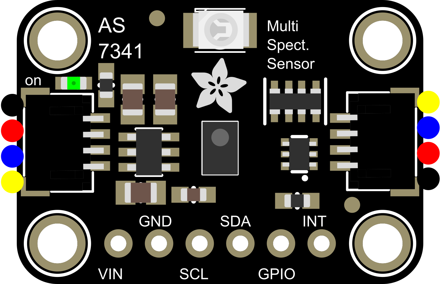
The Adafruit AS7341 is a highly versatile light and color sensor capable of detecting light intensity and color across multiple spectral bands. This sensor is designed for applications requiring precise light measurement, such as environmental monitoring, robotics, and smart lighting systems. Its compact design and advanced features make it ideal for integration into automation systems, IoT devices, and color-sensitive applications.

Explore Projects Built with Light/Color Sensor

Use Cirkit Designer to design, explore, and prototype these projects online. Some projects support real-time simulation. Click "Open Project" to start designing instantly!
Arduino UNO with TCS34725 Color Sensor and LDR Light Detection
Image of SSC: A project utilizing Light/Color Sensor  in a practical application
This circuit features an Arduino UNO microcontroller connected to an Adafruit TCS34725 RGB Color Sensor and a photocell (LDR) with a 10k Ohm resistor forming a voltage divider connected to the Arduino's analog input A0. The RGB sensor is interfaced with the Arduino via I2C communication, using SDA and SCL lines. The purpose of this circuit is likely to measure ambient light intensity with the photocell and detect colors with the RGB sensor, both interfaced with the Arduino for processing and potential output of the sensor data.
Cirkit Designer LogoOpen Project in Cirkit Designer
Arduino UNO and AS7262 Color Change Detection System with Bluetooth and OLED Display
Image of CAR project: A project utilizing Light/Color Sensor  in a practical application
This circuit is designed to detect color changes in a solution using a spectral sensor, time the change, provide a sound cue via a piezo buzzer, and send the timing data to a computer via a Bluetooth module. The Arduino UNO microcontroller coordinates the sensor readings, timing, and communication, while an OLED display and NeoPixel ring provide visual feedback.
Cirkit Designer LogoOpen Project in Cirkit Designer
Arduino Nano-Controlled Lighting System with Gesture and Sound Interaction
Image of 4 load controll using hand gesture and sound controll: A project utilizing Light/Color Sensor  in a practical application
This circuit features an Arduino Nano microcontroller interfaced with an APDS-9960 RGB and Gesture Sensor for color and gesture detection, and a KY-038 microphone module for sound detection. The Arduino controls a 4-channel relay module, which in turn switches four AC bulbs on and off. The 12V power supply is used to power the relay module, and the bulbs are connected to the normally open (N.O.) contacts of the relays, allowing the Arduino to control the lighting based on sensor inputs.
Cirkit Designer LogoOpen Project in Cirkit Designer
Arduino UNO-Based Color Sensor and Proximity Detection System with TCS3200 and Inductive Sensor
Image of 404 Wiring Schematic: A project utilizing Light/Color Sensor  in a practical application
This circuit integrates an Arduino UNO with a TCS3200 color sensor and an LJ18A3-H-ZBX inductive proximity sensor to detect colors and proximity. The Arduino processes the sensor data and controls an LED indicator, with resistors used for current limiting.
Cirkit Designer LogoOpen Project in Cirkit Designer

Explore Projects Built with Light/Color Sensor

Use Cirkit Designer to design, explore, and prototype these projects online. Some projects support real-time simulation. Click "Open Project" to start designing instantly!
Image of SSC: A project utilizing Light/Color Sensor  in a practical application
Arduino UNO with TCS34725 Color Sensor and LDR Light Detection
This circuit features an Arduino UNO microcontroller connected to an Adafruit TCS34725 RGB Color Sensor and a photocell (LDR) with a 10k Ohm resistor forming a voltage divider connected to the Arduino's analog input A0. The RGB sensor is interfaced with the Arduino via I2C communication, using SDA and SCL lines. The purpose of this circuit is likely to measure ambient light intensity with the photocell and detect colors with the RGB sensor, both interfaced with the Arduino for processing and potential output of the sensor data.
Cirkit Designer LogoOpen Project in Cirkit Designer
Image of CAR project: A project utilizing Light/Color Sensor  in a practical application
Arduino UNO and AS7262 Color Change Detection System with Bluetooth and OLED Display
This circuit is designed to detect color changes in a solution using a spectral sensor, time the change, provide a sound cue via a piezo buzzer, and send the timing data to a computer via a Bluetooth module. The Arduino UNO microcontroller coordinates the sensor readings, timing, and communication, while an OLED display and NeoPixel ring provide visual feedback.
Cirkit Designer LogoOpen Project in Cirkit Designer
Image of 4 load controll using hand gesture and sound controll: A project utilizing Light/Color Sensor  in a practical application
Arduino Nano-Controlled Lighting System with Gesture and Sound Interaction
This circuit features an Arduino Nano microcontroller interfaced with an APDS-9960 RGB and Gesture Sensor for color and gesture detection, and a KY-038 microphone module for sound detection. The Arduino controls a 4-channel relay module, which in turn switches four AC bulbs on and off. The 12V power supply is used to power the relay module, and the bulbs are connected to the normally open (N.O.) contacts of the relays, allowing the Arduino to control the lighting based on sensor inputs.
Cirkit Designer LogoOpen Project in Cirkit Designer
Image of 404 Wiring Schematic: A project utilizing Light/Color Sensor  in a practical application
Arduino UNO-Based Color Sensor and Proximity Detection System with TCS3200 and Inductive Sensor
This circuit integrates an Arduino UNO with a TCS3200 color sensor and an LJ18A3-H-ZBX inductive proximity sensor to detect colors and proximity. The Arduino processes the sensor data and controls an LED indicator, with resistors used for current limiting.
Cirkit Designer LogoOpen Project in Cirkit Designer

Common Applications and Use Cases

  • Ambient light sensing for smart lighting systems
  • Color detection in robotics and industrial automation
  • Environmental monitoring and agricultural systems
  • Display calibration and color matching
  • Scientific research and experimentation

Technical Specifications

The AS7341 sensor is equipped with advanced features for accurate light and color detection. Below are its key technical specifications:

Parameter Value
Manufacturer Adafruit
Part ID AS7341
Spectral Channels 10 (visible and near-infrared)
Spectral Range 350 nm to 1000 nm
Supply Voltage 1.8V (core), 3.3V (I/O)
Communication Interface I²C
I²C Address (Default) 0x39
Operating Temperature -40°C to +85°C
Power Consumption 0.7 mA (typical)
Dimensions 20mm x 17mm x 2mm

Pin Configuration and Descriptions

The AS7341 sensor module has the following pinout:

Pin Name Description
1 VIN Power supply input (3.3V or 5V)
2 GND Ground
3 SDA I²C data line
4 SCL I²C clock line
5 INT Interrupt output (optional, for event signaling)
6 LDR LED driver output (optional, for external LEDs)

Usage Instructions

How to Use the AS7341 in a Circuit

  1. Power the Sensor: Connect the VIN pin to a 3.3V or 5V power source and the GND pin to ground.
  2. I²C Communication: Connect the SDA and SCL pins to the corresponding I²C pins on your microcontroller (e.g., Arduino UNO).
  3. Optional Connections:
    • Use the INT pin to receive interrupt signals for specific events.
    • Connect the LDR pin to control an external LED for illumination.

Important Considerations and Best Practices

  • Voltage Levels: Ensure the I²C lines (SDA and SCL) operate at 3.3V logic levels. Use a level shifter if your microcontroller operates at 5V logic.
  • Pull-Up Resistors: The I²C bus requires pull-up resistors on the SDA and SCL lines. These are typically included on the breakout board.
  • Ambient Light: Avoid direct exposure to intense light sources, as this may saturate the sensor and affect accuracy.
  • Calibration: For precise measurements, calibrate the sensor in your specific environment.

Example Code for Arduino UNO

Below is an example of how to interface the AS7341 with an Arduino UNO using the Adafruit AS7341 library:

#include <Wire.h>
#include <Adafruit_AS7341.h>

// Create an instance of the AS7341 sensor
Adafruit_AS7341 as7341;

void setup() {
  Serial.begin(115200); // Initialize serial communication for debugging
  while (!Serial);      // Wait for the serial monitor to open

  // Initialize the sensor
  if (!as7341.begin()) {
    Serial.println("AS7341 not detected. Check connections!");
    while (1); // Halt execution if the sensor is not found
  }
  Serial.println("AS7341 initialized successfully!");
}

void loop() {
  // Read and print the light intensity for all 10 channels
  for (int i = 0; i < 10; i++) {
    uint16_t channelData = as7341.readChannel(i);
    Serial.print("Channel ");
    Serial.print(i);
    Serial.print(": ");
    Serial.println(channelData);
  }
  delay(1000); // Wait 1 second before the next reading
}

Notes on the Code

  • Install the Adafruit AS7341 library via the Arduino Library Manager before running the code.
  • The readChannel() function retrieves light intensity data for each spectral channel.

Troubleshooting and FAQs

Common Issues and Solutions

  1. Sensor Not Detected:

    • Cause: Incorrect I²C wiring or address mismatch.
    • Solution: Verify the SDA and SCL connections and ensure the I²C address is set to 0x39.
  2. Inaccurate Readings:

    • Cause: Ambient light interference or improper calibration.
    • Solution: Shield the sensor from direct light sources and perform calibration.
  3. No Data Output:

    • Cause: Library not installed or incorrect initialization.
    • Solution: Ensure the Adafruit AS7341 library is installed and the begin() function is called.

FAQs

Q: Can the AS7341 detect UV or IR light?
A: Yes, the AS7341 can detect near-infrared light (up to 1000 nm) but does not cover the UV spectrum below 350 nm.

Q: What is the purpose of the LDR pin?
A: The LDR pin is used to control an external LED for illumination, which can improve accuracy in low-light conditions.

Q: Can I use the AS7341 with a 5V microcontroller?
A: Yes, but you must use a level shifter for the I²C lines to ensure compatibility with the sensor's 3.3V logic levels.