How to Use WiFi Antenna: Examples, Pinouts, and Specs
Introduction
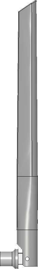
A WiFi Antenna is a crucial component in wireless communication systems. It is designed to transmit and receive radio frequency signals, which are used to facilitate WiFi connectivity between devices such as routers, access points, laptops, and smartphones. WiFi antennas come in various forms, including dipole, directional, and omnidirectional types, each suited for specific applications and environments.
Explore Projects Built with WiFi Antenna
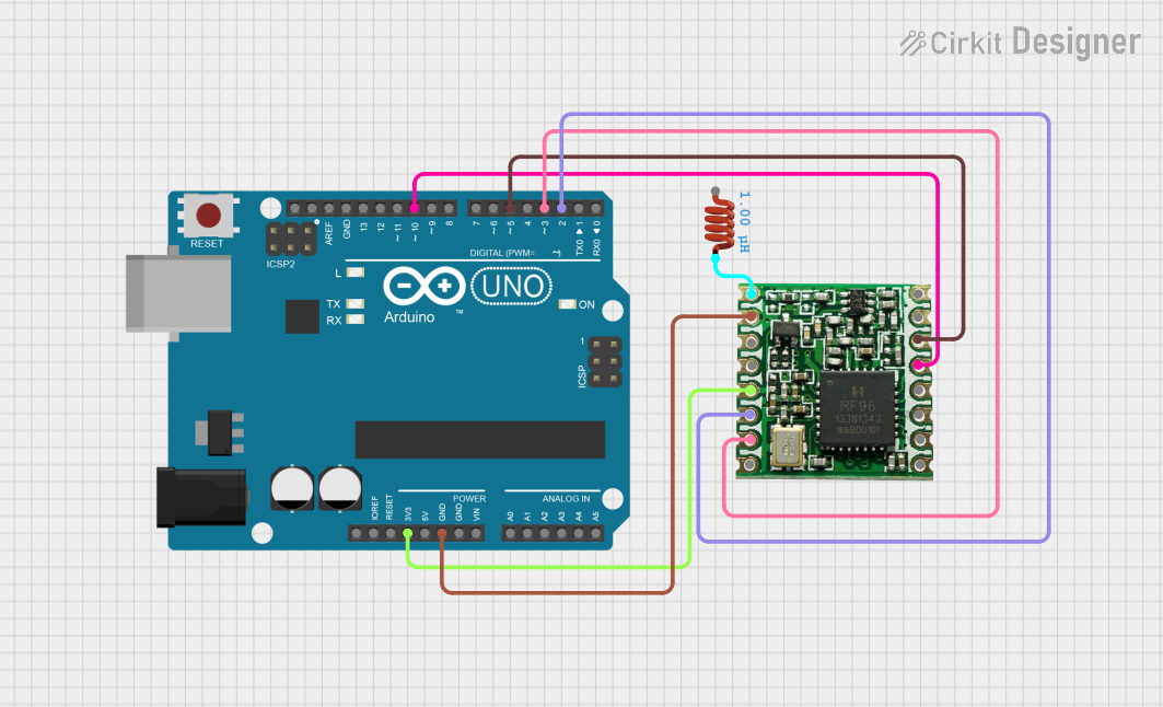
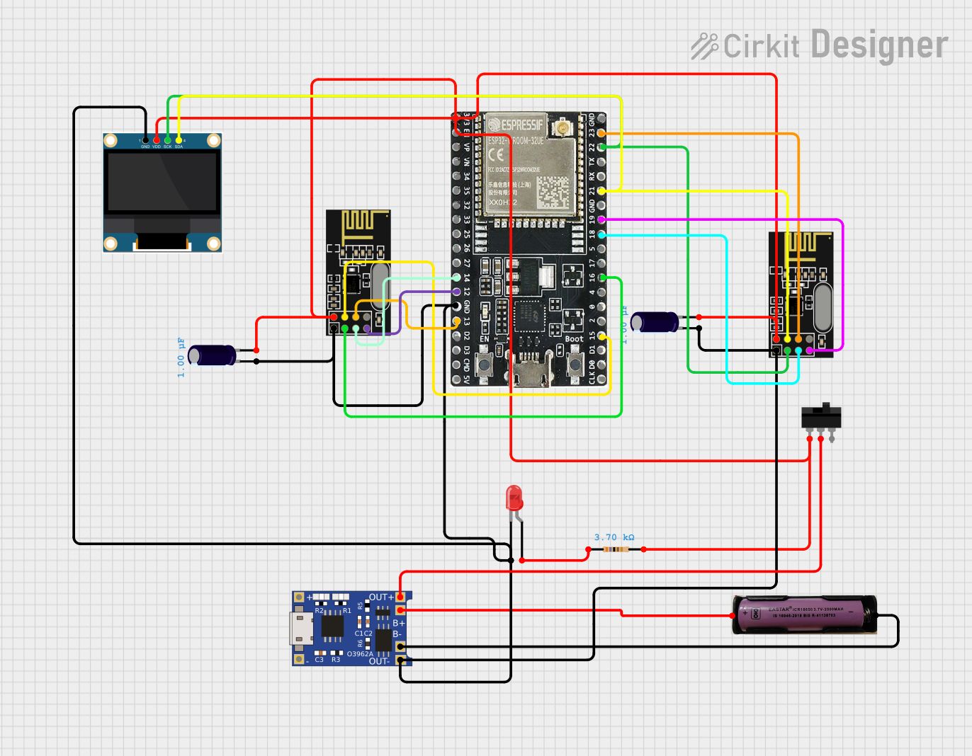


Explore Projects Built with WiFi Antenna
Common Applications and Use Cases
- Home and office wireless networks
- Public WiFi hotspots
- Wireless bridges between buildings
- IoT (Internet of Things) devices
- Drones and remote-controlled vehicles
- Mobile devices with WiFi capabilities
Technical Specifications
Key Technical Details
- Frequency Range: Typically 2.4 GHz and 5 GHz bands
- Impedance: Standard 50 Ohms
- VSWR (Voltage Standing Wave Ratio): Ideally less than 2:1
- Gain: Measured in dBi, varies depending on antenna type
- Polarization: Linear (vertical or horizontal), Circular
- Radiation Pattern: Directional or Omnidirectional
Pin Configuration and Descriptions
Since a WiFi antenna does not have a pin configuration like an integrated circuit, this section is not applicable. Instead, WiFi antennas typically have connector types that are used to interface with wireless devices. Common connectors include:
| Connector Type | Description |
|---|---|
| SMA (SubMiniature version A) | A screw-on mechanism that is common for router and access point antennas. |
| RP-SMA (Reverse Polarity SMA) | Similar to SMA but with reverse polarity; commonly used in WiFi equipment. |
| U.FL (Micro-Coaxial) | A miniature RF connector for high-frequency signals, often found in laptops and embedded systems. |
| N-Type | A durable, weatherproof connector used in outdoor applications. |
Usage Instructions
How to Use the Component in a Circuit
- Identify the Connector Type: Ensure the antenna's connector matches the device's connector.
- Connect the Antenna: Screw or snap the antenna onto the device's antenna connector.
- Position the Antenna: For directional antennas, aim towards the area of coverage. For omnidirectional antennas, place centrally.
- Power On the Device: Once connected, power on the device to enable the antenna to begin transmitting and receiving signals.
Important Considerations and Best Practices
- Antenna Placement: Keep the antenna away from metal objects and electronic interference for optimal performance.
- Orientation: Align the antenna according to its polarization for better signal strength.
- Cable Length: Use the shortest possible cable between the antenna and the device to minimize signal loss.
- Outdoor Use: For outdoor antennas, ensure they are weatherproof and securely mounted.
Troubleshooting and FAQs
Common Issues Users Might Face
- Poor Signal Strength: This could be due to obstructions, interference, or incorrect antenna placement.
- Intermittent Connectivity: Check for loose connections or damage to the antenna or cables.
- Limited Range: The antenna may have insufficient gain for the desired coverage area.
Solutions and Tips for Troubleshooting
- Reposition the Antenna: Adjust the location and orientation to avoid obstructions and interference.
- Check Connections: Ensure all connectors are secure and the antenna is properly attached.
- Upgrade Antenna: Consider using an antenna with higher gain or a different radiation pattern to extend range.
FAQs
Q: Can I use any WiFi antenna with my device? A: The antenna must be compatible with the device's frequency and have the correct connector type.
Q: Does the length of the antenna matter? A: Yes, the length correlates with the wavelength of the frequency and can affect performance.
Q: How can I extend the range of my WiFi network? A: Use a high-gain antenna, add a repeater, or reposition the current antenna to a more central location.
Q: Can I use multiple antennas on one device? A: Yes, if the device supports multiple antennas (MIMO technology), this can improve performance and range.
Note: This documentation is a general guide and may not cover all aspects of WiFi antenna usage. For device-specific instructions, consult the manufacturer's manual.