
How to Use Raspberry Pi Zero: Examples, Pinouts, and Specs
 Design with Raspberry Pi Zero in Cirkit Designer
Introduction
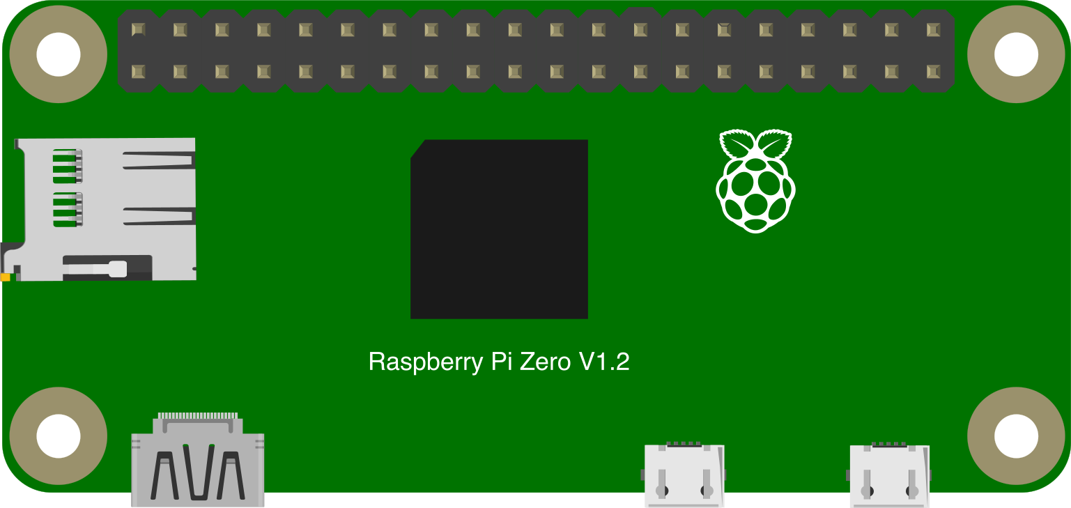
The Raspberry Pi Zero is a compact, low-cost single-board computer designed for embedded projects and Internet of Things (IoT) applications. It features a 1 GHz ARM processor, 512 MB of RAM, and a set of GPIO (General Purpose Input/Output) pins for hardware interfacing. Despite its small size, the Raspberry Pi Zero is a powerful tool for hobbyists, educators, and professionals looking to create innovative and efficient electronic projects.
Explore Projects Built with Raspberry Pi Zero
 Open Project in Cirkit Designer
 Open Project in Cirkit Designer
 Open Project in Cirkit Designer
 Open Project in Cirkit Designer
Explore Projects Built with Raspberry Pi Zero
Open Project in Cirkit DesignerOpen Project in Cirkit DesignerOpen Project in Cirkit DesignerOpen Project in Cirkit DesignerCommon Applications and Use Cases
- IoT devices and smart home automation
- Robotics and motor control
- Media streaming and playback
- Portable gaming consoles
- Data logging and environmental monitoring
- Prototyping and educational projects
Technical Specifications
Key Technical Details
- Processor: Broadcom BCM2835, 1 GHz ARM11 core
- RAM: 512 MB LPDDR2
- Power Supply: 5V via micro-USB (minimum 1.2A recommended)
- Connectivity: Mini HDMI, micro-USB OTG, and GPIO header
- Storage: MicroSD card slot for operating system and data
- GPIO: 40-pin header (unpopulated)
- Video Output: Mini HDMI (1080p at 60 fps)
- Dimensions: 65mm × 30mm × 5mm
- Weight: 9 grams
Pin Configuration and Descriptions
The Raspberry Pi Zero features a 40-pin GPIO header. Below is a table summarizing the pin configuration:
| Pin Number | Pin Name | Description |
|---|---|---|
| 1 | 3.3V | 3.3V Power Output |
| 2 | 5V | 5V Power Output |
| 3 | GPIO2 (SDA1) | I2C Data Line |
| 4 | 5V | 5V Power Output |
| 5 | GPIO3 (SCL1) | I2C Clock Line |
| 6 | GND | Ground |
| 7 | GPIO4 | General Purpose I/O |
| 8 | GPIO14 (TXD) | UART Transmit |
| 9 | GND | Ground |
| 10 | GPIO15 (RXD) | UART Receive |
| ... | ... | ... |
| 39 | GND | Ground |
| 40 | GPIO21 (SDA0) | I2C Data Line |
Note: Only a subset of pins is shown here. Refer to the official Raspberry Pi GPIO pinout diagram for the full list.
Usage Instructions
How to Use the Raspberry Pi Zero in a Circuit
Powering the Raspberry Pi Zero:
- Use a 5V micro-USB power supply capable of delivering at least 1.2A.
- Connect the power supply to the micro-USB power port labeled "PWR IN."
Connecting Peripherals:
- Use a mini HDMI cable to connect the Raspberry Pi Zero to a monitor.
- Attach a USB OTG adapter to connect peripherals like a keyboard, mouse, or USB hub.
Interfacing with GPIO:
- Solder a 40-pin header to the GPIO pads if required.
- Use jumper wires to connect the GPIO pins to external components like LEDs, sensors, or motors.
Installing the Operating System:
- Download the Raspberry Pi OS image from the official website.
- Flash the image onto a microSD card using tools like Balena Etcher.
- Insert the microSD card into the Raspberry Pi Zero's card slot.
Important Considerations and Best Practices
- Ensure proper heat dissipation if the Raspberry Pi Zero is used in high-performance applications.
- Avoid shorting GPIO pins or connecting them to voltages higher than 3.3V.
- Use level shifters when interfacing with 5V logic devices.
- Always shut down the Raspberry Pi Zero properly to prevent data corruption on the microSD card.
Example: Blinking an LED with GPIO and Arduino UNO
The Raspberry Pi Zero can control an LED using its GPIO pins. Below is an example Python script for blinking an LED connected to GPIO17 (pin 11):
Import the GPIO and time libraries
import RPi.GPIO as GPIO import time
Set up GPIO mode and pin
GPIO.setmode(GPIO.BCM) # Use Broadcom pin numbering GPIO.setup(17, GPIO.OUT) # Set GPIO17 as an output pin
try: while True: GPIO.output(17, GPIO.HIGH) # Turn the LED on time.sleep(1) # Wait for 1 second GPIO.output(17, GPIO.LOW) # Turn the LED off time.sleep(1) # Wait for 1 second except KeyboardInterrupt: # Clean up GPIO settings on exit GPIO.cleanup()
> **Note**: Install the `RPi.GPIO` library using `pip install RPi.GPIO` if it is not already installed.
Troubleshooting and FAQs
Common Issues and Solutions
The Raspberry Pi Zero does not boot:
- Ensure the microSD card is properly inserted and contains a valid OS image.
- Verify that the power supply provides sufficient current (at least 1.2A).
No display on the monitor:
- Check the mini HDMI cable connection.
- Ensure the monitor supports the resolution and refresh rate of the Raspberry Pi Zero.
GPIO pins not working:
- Confirm that the correct GPIO pin numbering is used in the code.
- Check for loose connections or damaged components.
Overheating:
- Use a heatsink or active cooling if the Raspberry Pi Zero operates under heavy load.
FAQs
Can the Raspberry Pi Zero connect to Wi-Fi?
- The Raspberry Pi Zero does not have built-in Wi-Fi. Use a USB Wi-Fi dongle or upgrade to the Raspberry Pi Zero W, which includes Wi-Fi and Bluetooth.
What is the maximum current output of the GPIO pins?
- Each GPIO pin can source or sink up to 16 mA, with a total maximum current of 50 mA across all GPIO pins.
Can I power the Raspberry Pi Zero through the GPIO pins?
- Yes, you can supply 5V to the 5V pin and GND to a ground pin, but ensure proper voltage regulation and polarity.
This concludes the documentation for the Raspberry Pi Zero. For further details, refer to the official Raspberry Pi documentation and community forums.