How to Use ponte h: Examples, Pinouts, and Specs
Introduction
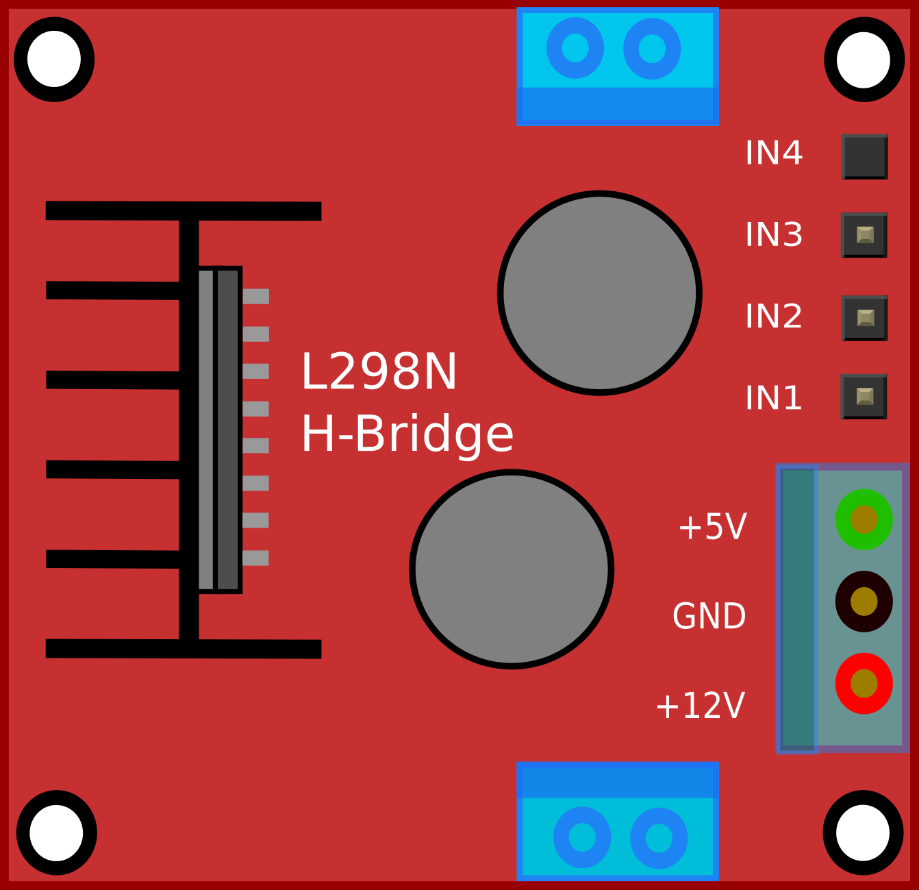
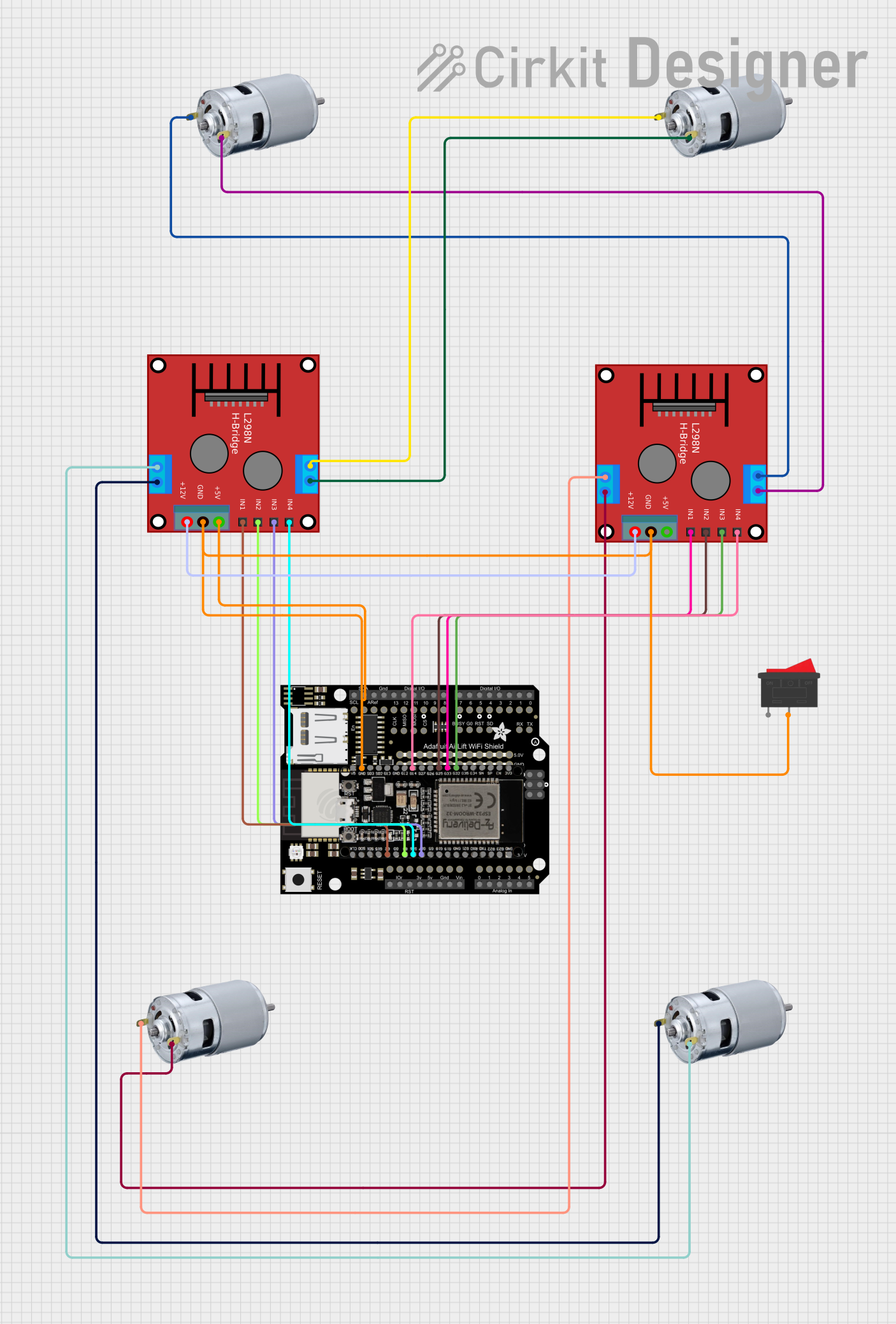
An H-Bridge Motor Driver, commonly referred to as a "Ponte H," is an electronic circuit that enables a voltage to be applied across a load in either direction. These circuits are widely used in robotics and automation to control the direction and speed of DC motors. The H-Bridge can drive a motor to spin in both clockwise and counterclockwise directions by reversing the current flow through the motor.
Explore Projects Built with ponte h
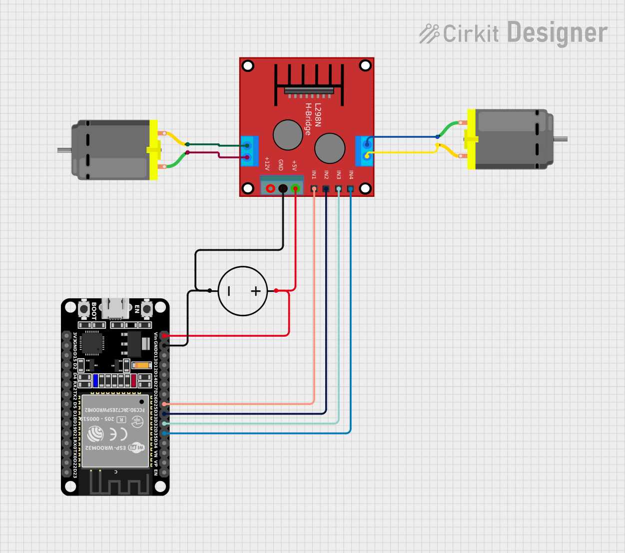
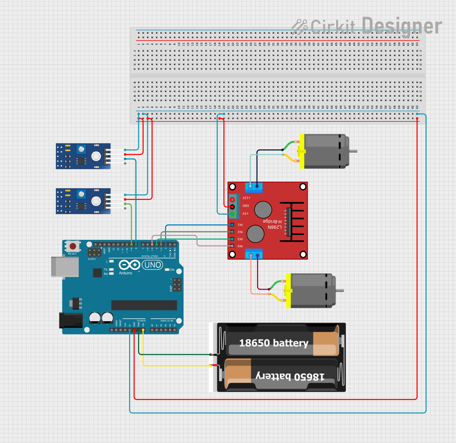
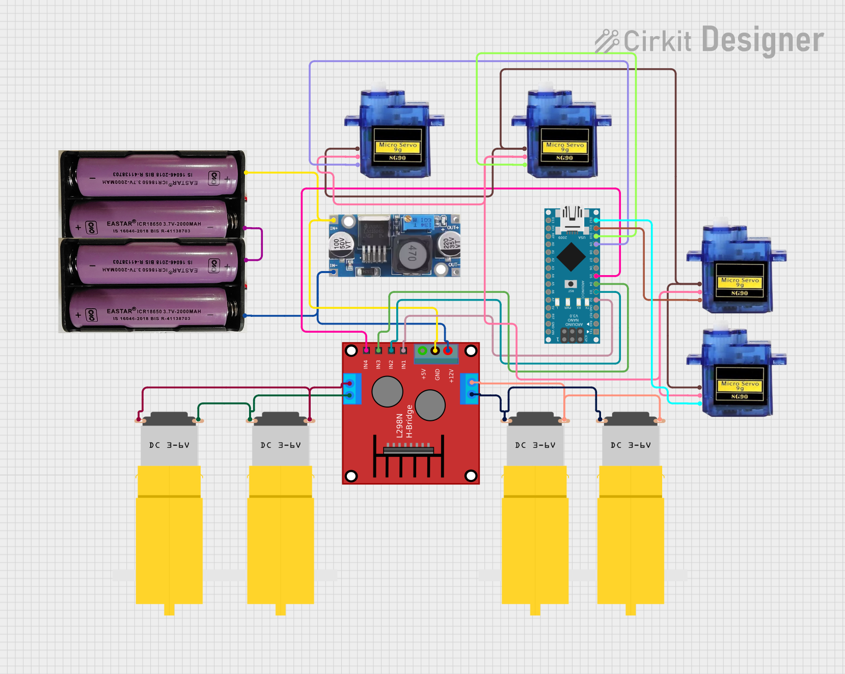
Explore Projects Built with ponte h
Common Applications and Use Cases
- Robotics: to control the wheel motors.
- Automation systems: for conveyor belt direction control.
- Electric vehicles: to control the propulsion motors.
- Hobby projects: in RC cars, drones, and other DIY projects.
Technical Specifications
Key Technical Details
- Operating Voltage Range: Typically 5V to 35V (varies by model)
- Output Current: Up to 2A per channel (varies by model)
- Logic Voltage: 5V (compatible with most microcontrollers like Arduino)
Pin Configuration and Descriptions
| Pin Number | Pin Name | Description |
|---|---|---|
| 1 | Vcc1 | Logic power supply (5V) |
| 2 | Input 1 | Controls the logic for motor direction |
| 3 | Input 2 | Controls the logic for motor direction |
| 4 | Vcc2 | Motor power supply (up to 35V) |
| 5 | Output 1 | Connected to one terminal of the motor |
| 6 | Output 2 | Connected to the other terminal of the motor |
| 7 | Ground | Common ground for logic and motor power |
Usage Instructions
How to Use the Component in a Circuit
- Connect Vcc1 to the 5V power supply from the microcontroller.
- Connect Vcc2 to the positive terminal of the motor power supply.
- Connect Ground to the common ground of the power supplies and microcontroller.
- Connect Output 1 and Output 2 to the motor terminals.
- Input 1 and Input 2 are connected to the digital output pins of the microcontroller.
Important Considerations and Best Practices
- Ensure that the power supply voltage and current do not exceed the specifications of the H-Bridge.
- Use a separate power supply for the motor (Vcc2) and the logic (Vcc1) to prevent noise issues.
- Always include a flyback diode across the motor terminals to protect the H-Bridge from voltage spikes.
- Avoid switching the inputs simultaneously to prevent a short circuit (known as "shoot-through").
Example Code for Arduino UNO
// Define the motor control pins
const int input1 = 2;
const int input2 = 3;

void setup() {
  // Set the motor control pins as outputs
  pinMode(input1, OUTPUT);
  pinMode(input2, OUTPUT);
}

void loop() {
  // Spin motor in one direction
  digitalWrite(input1, HIGH);
  digitalWrite(input2, LOW);
  delay(1000); // Run the motor for 1 second

  // Stop the motor
  digitalWrite(input1, LOW);
  digitalWrite(input2, LOW);
  delay(1000); // Stop the motor for 1 second

  // Spin motor in the opposite direction
  digitalWrite(input1, LOW);
  digitalWrite(input2, HIGH);
  delay(1000); // Run the motor for 1 second

  // Stop the motor
  digitalWrite(input1, LOW);
  digitalWrite(input2, LOW);
  delay(1000); // Stop the motor for 1 second
}
Troubleshooting and FAQs
Common Issues Users Might Face
- Motor not spinning: Check the power supply and connections.
- Motor spinning in one direction only: Verify the logic signals from the microcontroller.
- Overheating: Ensure the current does not exceed the H-Bridge's rating.
Solutions and Tips for Troubleshooting
- Double-check wiring, especially the motor and power connections.
- Use a multimeter to verify the voltage at the inputs and outputs.
- Implement a proper cooling mechanism if the H-Bridge overheats.
FAQs
Q: Can I control the speed of the motor using an H-Bridge? A: Yes, by using PWM (Pulse Width Modulation) on the input pins, you can control the motor's speed.
Q: What happens if I apply the same logic level to both inputs? A: Applying the same logic level to both inputs will stop the motor. However, ensure not to apply a high level to both inputs simultaneously as it may cause a short circuit.
Q: Can I use the H-Bridge with a microcontroller operating at 3.3V? A: It depends on the H-Bridge model. Some are compatible with 3.3V logic levels, while others require level shifting.
This documentation provides a comprehensive guide to using an H-Bridge Motor Driver in various applications. Always refer to the specific datasheet of the H-Bridge model you are using for precise specifications and recommendations.