How to Use MICS2714: Examples, Pinouts, and Specs
Introduction
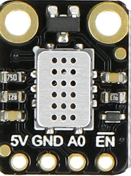
The MICS-2714 is a compact, high-sensitivity chemiresistor sensor designed for the detection of Carbon Monoxide (CO) in the air. It is capable of sensing CO gas concentrations from 1 to 1000 parts per million (ppm), making it suitable for a wide range of safety and environmental monitoring applications. Due to its low power requirements and tunable sensitivity, the MICS-2714 is an excellent choice for portable and fixed gas detection systems.
Explore Projects Built with MICS2714
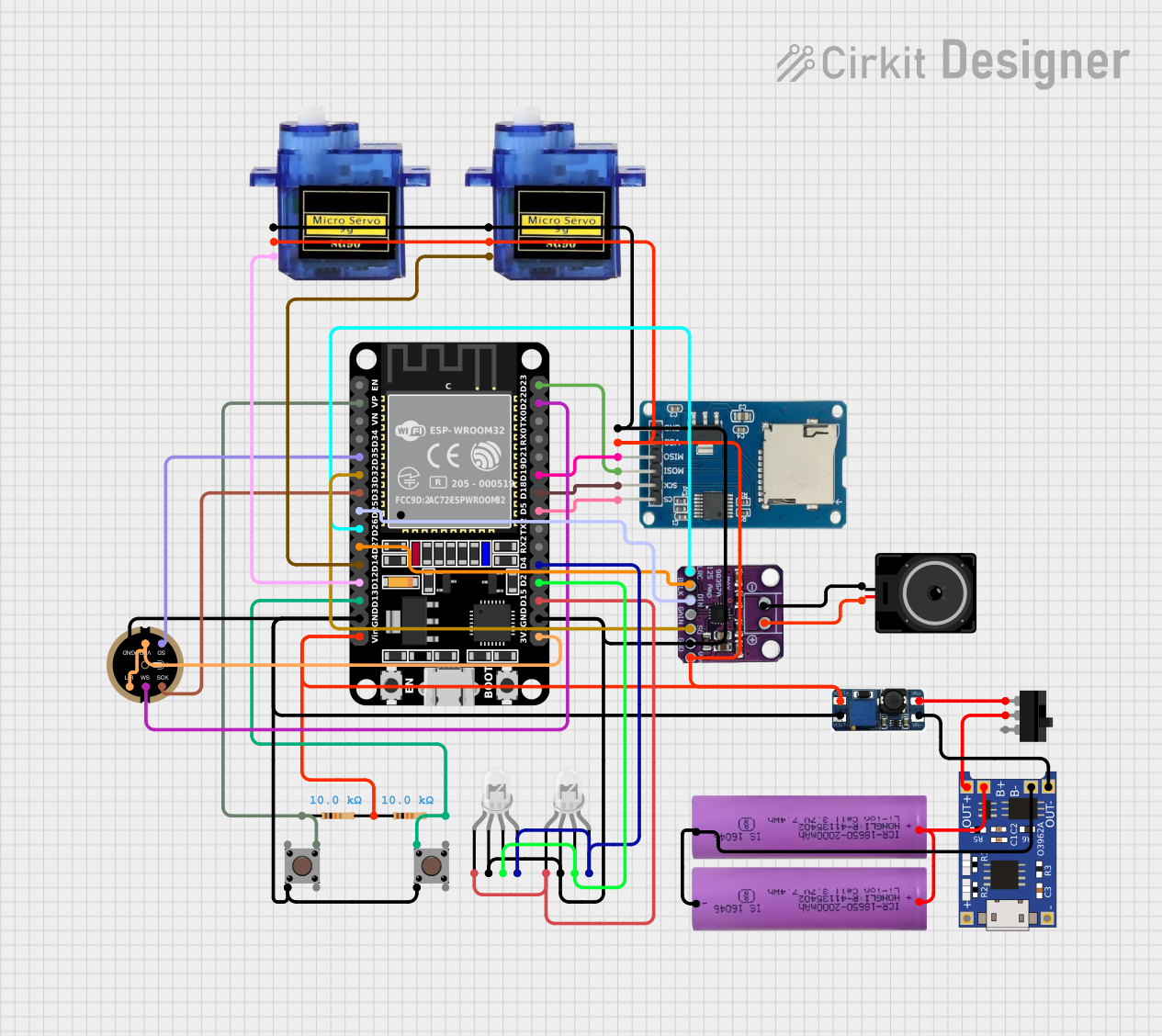
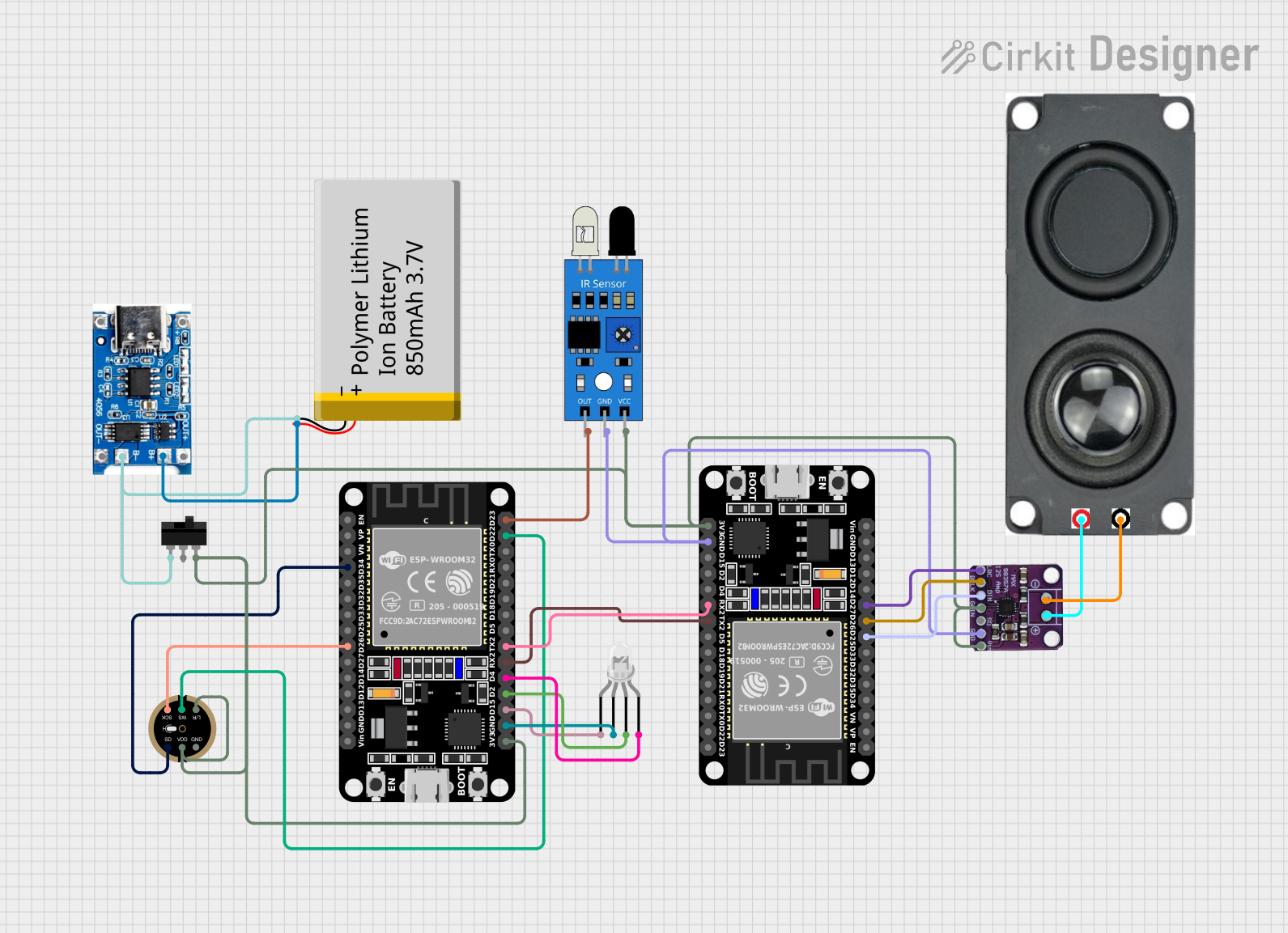
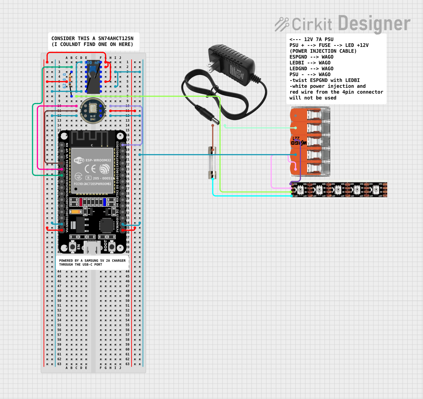
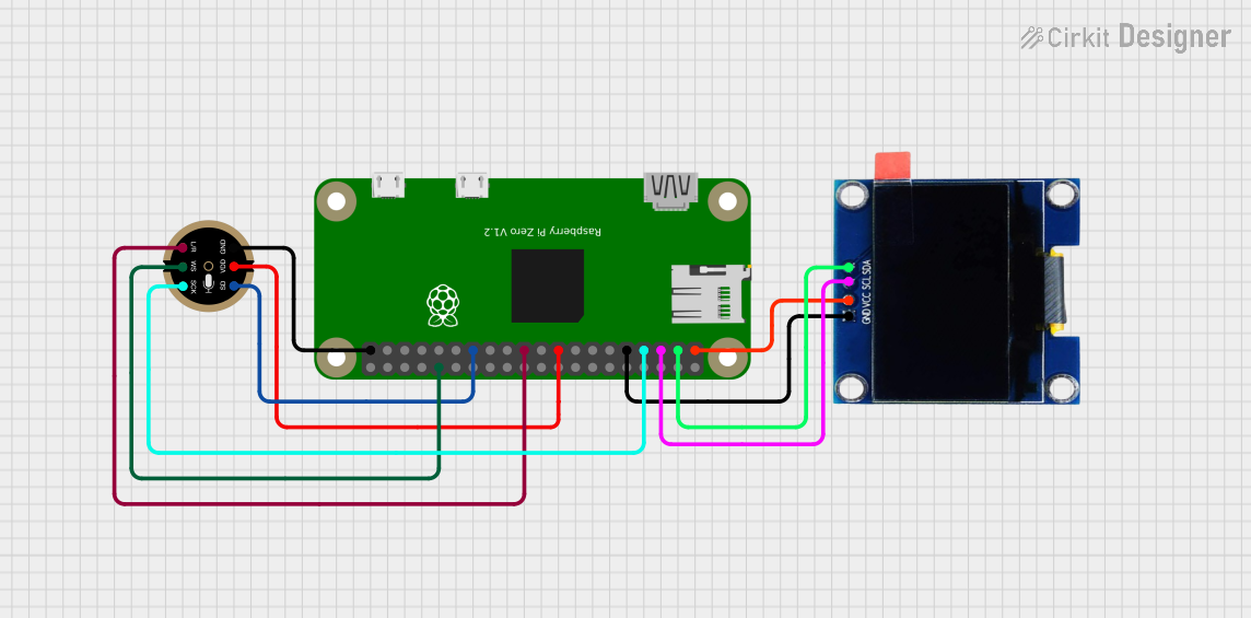
Explore Projects Built with MICS2714
Common Applications
- Residential and commercial CO detectors
- Air quality monitoring
- Industrial safety systems
- Environmental monitoring
- HVAC systems to ensure air quality
Technical Specifications
Key Technical Details
- Nominal Operating Voltage: 1.8V
- Heater Voltage: 5V ±0.2V
- Heater Power Consumption: 56mW (typical)
- Target Gas: Carbon Monoxide (CO)
- Measurement Range: 1 to 1000 ppm
- Sensitivity: Variable (dependent on load resistance)
- Response Time (t90): < 30 seconds
- Operating Temperature Range: -20°C to +50°C
- Storage Temperature Range: -20°C to +40°C
- Humidity Range: 15% to 95% RH non-condensing
Pin Configuration and Descriptions
| Pin Number | Description | Notes |
|---|---|---|
| 1 | Heater Positive (H+) | Connect to 5V supply |
| 2 | Sensor Output (S) | Analog voltage output |
| 3 | Heater Negative (H-) | Connect to ground |
| 4 | Sensor Ground (GND) | Connect to ground |
Usage Instructions
Integration into a Circuit
Powering the Heater: Apply a 5V supply to the heater pins (H+ and H-) to activate the sensor. Ensure that the power supply can deliver the necessary current without significant voltage drop.
Reading Sensor Output: Connect the sensor output (S) to an analog input of a microcontroller, such as an Arduino UNO, to read the varying voltage corresponding to different CO concentrations.
Load Resistor: A load resistor (RL) is required between the sensor output (S) and ground (GND) to set the sensitivity of the sensor. The value of RL can be adjusted based on the desired sensitivity and response time.
Important Considerations
Preheating: The sensor requires a preheating time of at least 48 hours for initial use and 5 minutes after each subsequent power-up to stabilize and provide accurate readings.
Calibration: The sensor must be calibrated in the environment where it will be used, or against a known concentration of CO gas to ensure accurate readings.
Environmental Factors: The sensor's performance may be affected by changes in temperature and humidity. Compensation may be required for accurate gas concentration readings.
Safety: Always follow safety guidelines when working with gas sensors and ensure proper ventilation in the testing area.
Example Arduino Code
// MICS-2714 CO Sensor Example for Arduino UNO
const int sensorPin = A0; // Sensor output connected to analog pin A0
const float supplyVoltage = 5.0; // Supply voltage for the sensor heater

void setup() {
  Serial.begin(9600); // Start serial communication at 9600 baud
  pinMode(sensorPin, INPUT); // Set sensor pin as input
}

void loop() {
  int sensorValue = analogRead(sensorPin); // Read the sensor output
  float sensorVoltage = sensorValue * (supplyVoltage / 1023.0); // Convert to voltage
  // TODO: Implement calibration and conversion to ppm here

  Serial.print("Sensor Voltage: ");
  Serial.print(sensorVoltage);
  Serial.println(" V");
  // Add a delay between readings for stability
  delay(1000);
}
Troubleshooting and FAQs
Common Issues
Inaccurate Readings: Ensure the sensor has been properly preheated and calibrated. Check for any environmental factors that may affect the sensor's performance.
No Output Voltage: Verify that the heater is powered with 5V and the sensor output is correctly connected to the analog input.
Sensor Not Responding: Check for any loose connections and ensure the sensor is not exposed to contaminants that could damage the sensor.
Solutions and Tips
Preheating: Always allow the sensor to preheat for the recommended time before taking measurements.
Calibration: Perform regular calibrations, especially if the sensor is moved to a different environment.
Load Resistor: Experiment with different load resistor values to find the optimal balance between sensitivity and response time.
FAQs
Q: Can the MICS-2714 sensor detect gases other than CO?
A: The MICS-2714 is specifically designed for CO detection. While it may respond to other gases, it is not recommended for detecting gases other than CO.
Q: How often should the sensor be calibrated?
A: Calibration frequency depends on the application and environmental conditions. It is generally recommended to calibrate the sensor upon initial setup and periodically thereafter.
Q: What is the lifespan of the MICS-2714 sensor?
A: The lifespan can vary based on usage and environmental conditions. Typically, the sensor can last several years with proper maintenance and calibration.
Q: Is the MICS-2714 sensor waterproof?
A: No, the MICS-2714 is not waterproof. It should be protected from moisture and operated within the specified humidity range.