How to Use INMP441 FRONT MIC: Examples, Pinouts, and Specs
Introduction
The INMP441 Front Mic is a high-performance, low-power, omnidirectional, MEMS (MicroElectroMechanical Systems) microphone with a digital I2S (Inter-IC Sound) interface. This ultra-low noise microphone is designed for high-quality audio capture and is commonly used in smartphones, tablets, laptops, and other portable devices, as well as in smart home applications like voice assistants and IoT devices.
Explore Projects Built with INMP441 FRONT MIC
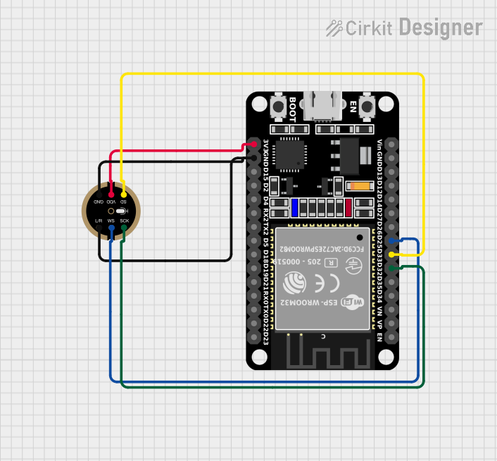
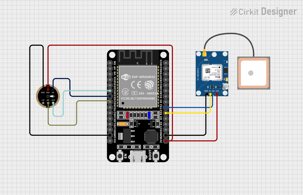
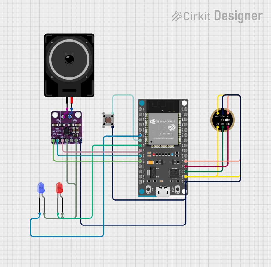
Explore Projects Built with INMP441 FRONT MIC
Common Applications and Use Cases
- Mobile devices (smartphones, tablets)
- Laptops and portable computers
- Smart home devices (voice assistants, smart speakers)
- IoT devices with voice capture capabilities
- Audio recording equipment
- Noise measurement and analysis tools
Technical Specifications
Key Technical Details
- Acoustic Overload Point: 120 dBSPL
- SNR: 61 dBA
- Sensitivity: -26 dBFS
- Power Supply: 1.8V
- Current Consumption: 1.3 mA (typical)
- Extended Frequency Response: 60 Hz to 15 kHz
- Interface: Digital I2S
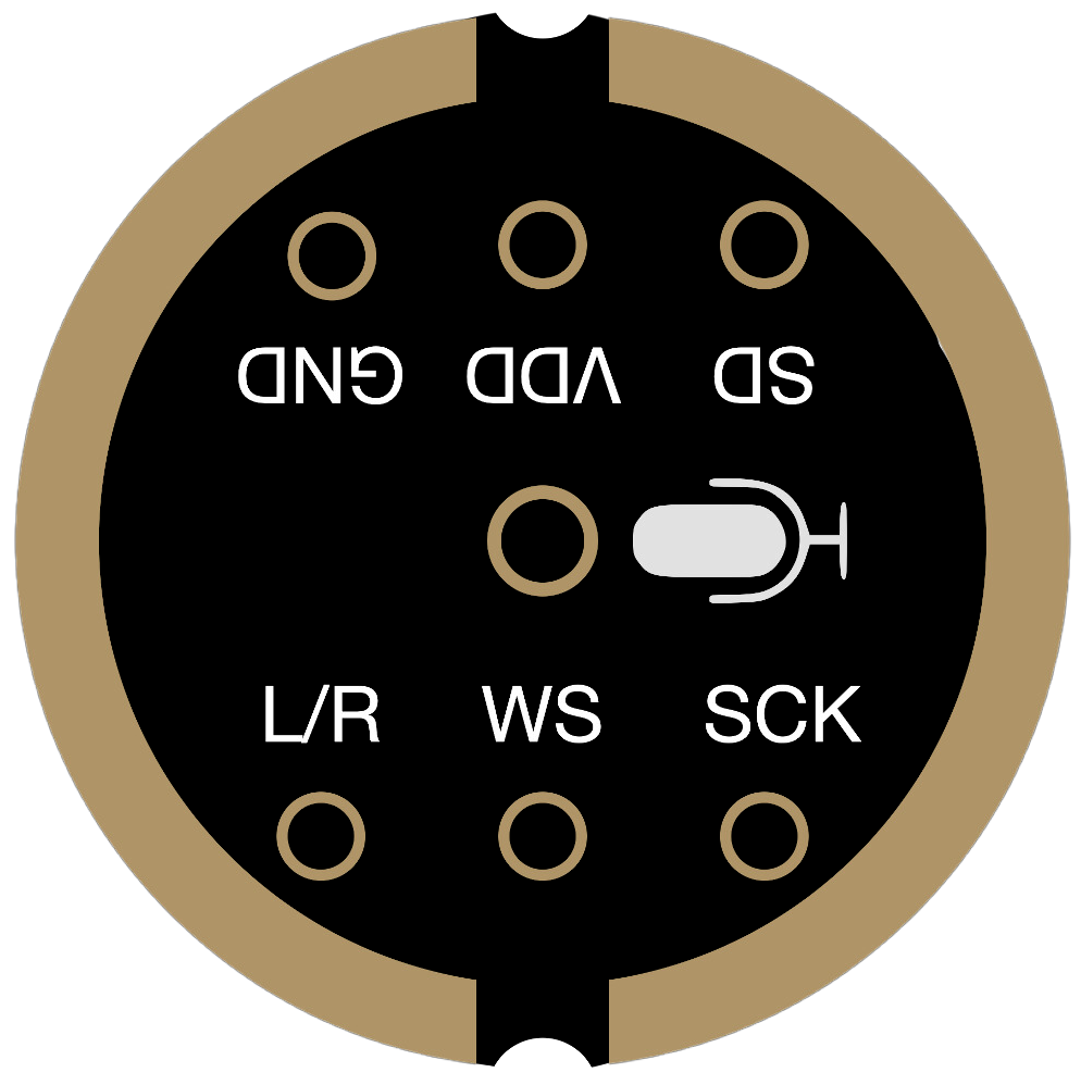
Pin Configuration and Descriptions
| Pin Number | Name | Description |
|---|---|---|
| 1 | L/R | Left/Right Channel Select |
| 2 | GND | Ground Connection |
| 3 | VDD | Power Supply (1.8V) |
| 4 | SD | Serial Data Output |
| 5 | SCK | Serial Clock for I2S |
| 6 | WS | Word Select for I2S |
Usage Instructions
How to Use the Component in a Circuit
- Power Supply: Connect the VDD pin to a 1.8V power source and the GND pin to the ground.
- I2S Interface: Connect the SD, SCK, and WS pins to the corresponding I2S interface pins on your microcontroller or processor.
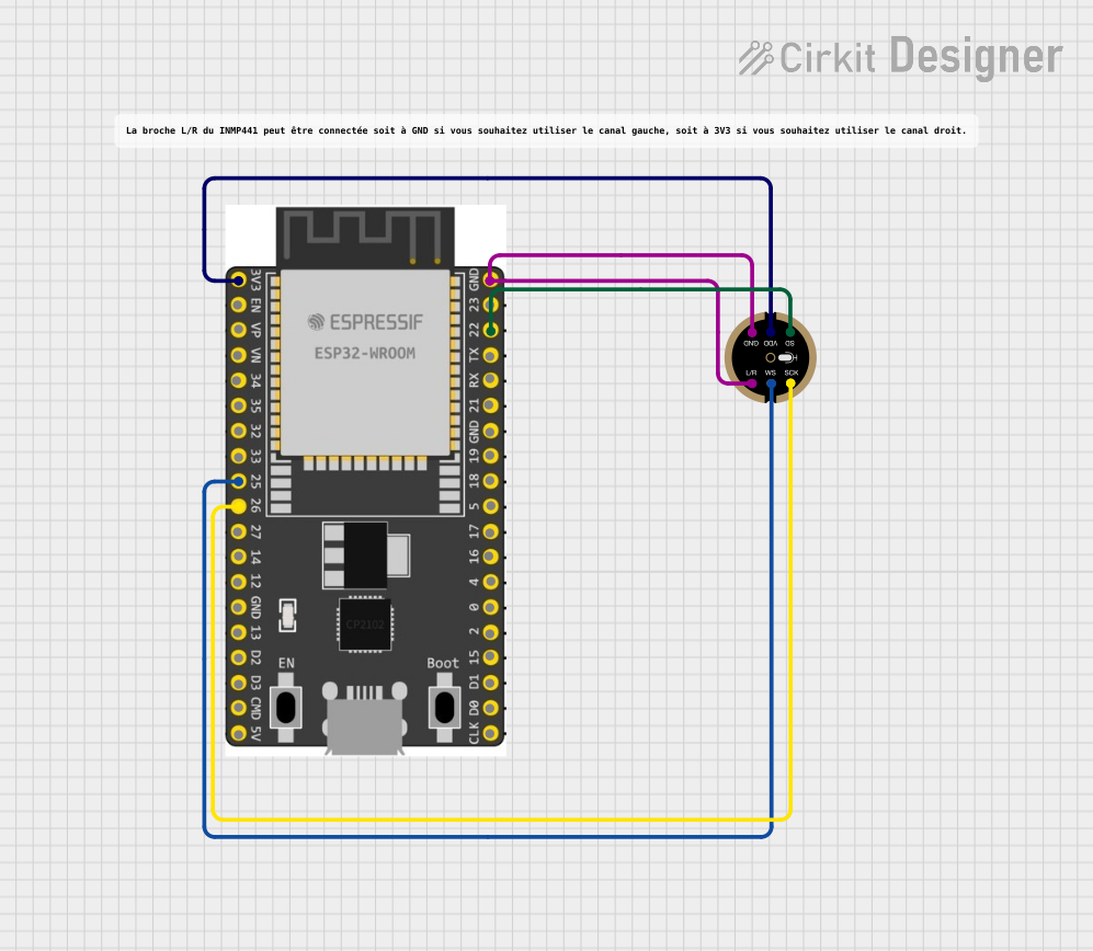
- Channel Selection: The L/R pin is used to select the left or right channel for stereo applications. Connect this pin to ground for left channel or leave it floating for right channel.
Important Considerations and Best Practices
- Ensure that the power supply is stable and clean to avoid noise in the audio signal.
- Use proper decoupling capacitors close to the VDD pin to minimize power supply noise.
- Keep the microphone away from sources of mechanical vibration to prevent false signals.
- Avoid running the I2S signal lines parallel to high-current traces to reduce the risk of electromagnetic interference.
Example Code for Arduino UNO
#include <I2S.h>

// Define the I2S pins for the Arduino UNO
const int i2s_ws_pin = 2;   // Word Select (L/R Clock)
const int i2s_sck_pin = 3;  // Serial Clock
const int i2s_sd_pin = 4;   // Serial Data

void setup() {
  // Initialize the I2S interface
  I2S.begin(I2S_PHILIPS_MODE, 16000, 16);
  pinMode(i2s_ws_pin, OUTPUT);
  pinMode(i2s_sck_pin, OUTPUT);
  pinMode(i2s_sd_pin, INPUT);
}

void loop() {
  // Read data from the INMP441 microphone
  long sample = I2S.read();

  // Process the sample if needed
  // ...

  // For demonstration purposes, we'll just print the sample value
  Serial.println(sample);
}
Note: The Arduino UNO does not natively support I2S, so an external I2S interface or shield is required to use the INMP441 with it.
Troubleshooting and FAQs
Common Issues
- No Audio Output: Ensure that the microphone is properly powered and that the I2S interface is correctly configured.
- Distorted Audio: Check for loose connections and ensure that the power supply is stable.
- Low Volume: Verify that the microphone's orientation is correct and that it is not obstructed.
Solutions and Tips for Troubleshooting
- Double-check wiring and solder joints for any potential issues.
- Use an oscilloscope to verify that the I2S clock and data signals are being transmitted correctly.
- Ensure that the audio processing system is configured to handle the I2S data format provided by the INMP441.
FAQs
Q: Can the INMP441 be used with a 3.3V power supply? A: No, the INMP441 is designed to operate at 1.8V. Using a higher voltage may damage the component.
Q: Is the INMP441 capable of stereo recording? A: Yes, two INMP441 microphones can be configured for stereo recording by setting one to the left and the other to the right channel using the L/R pin.
Q: How can I reduce noise in my audio recordings? A: Ensure that the power supply is clean, use proper decoupling techniques, and keep the microphone away from noise sources such as motors or high-frequency signals.