How to Use AD9833 function generator: Examples, Pinouts, and Specs
Introduction
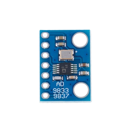
The AD9833 is a highly versatile programmable waveform generator capable of producing sine, square, and triangular waveforms. It features a frequency resolution of up to 0.1 Hz, making it ideal for applications requiring precise signal generation. This compact and efficient device is commonly used in signal processing, testing, and measurement systems, as well as in communication systems and audio applications.
Explore Projects Built with AD9833 function generator
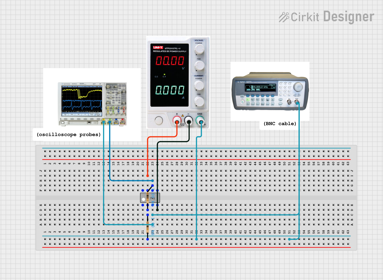
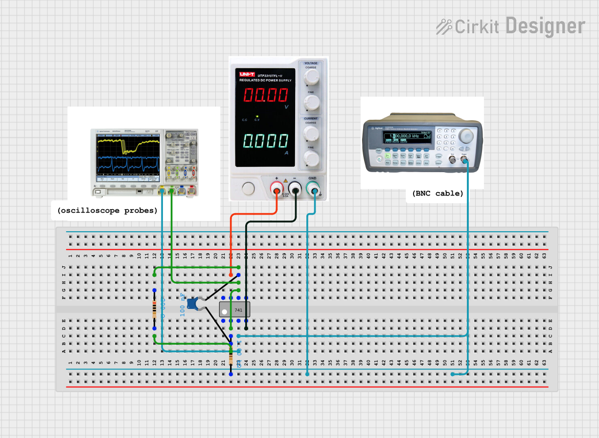


Explore Projects Built with AD9833 function generator
Common Applications
- Signal processing and waveform generation
- Function generators for testing and measurement
- Frequency modulation and phase modulation systems
- Audio signal generation
- Communication systems
Technical Specifications
The AD9833 is a low-power, highly integrated Direct Digital Synthesizer (DDS) with the following key specifications:
| Parameter | Value |
|---|---|
| Supply Voltage | 2.3 V to 5.5 V |
| Power Consumption | 20 mW (typical at 3.3 V) |
| Frequency Resolution | 0.1 Hz |
| Maximum Output Frequency | 12.5 MHz |
| Waveform Types | Sine, Square, Triangular |
| Communication Interface | Serial Peripheral Interface (SPI) |
| Package Type | 10-lead MSOP or 10-lead LFCSP |
Pin Configuration and Descriptions
The AD9833 has 10 pins, as described in the table below:
| Pin Number | Pin Name | Description |
|---|---|---|
| 1 | FSYNC | Active low chip select for SPI communication |
| 2 | SCLK | Serial clock input for SPI communication |
| 3 | SDATA | Serial data input for SPI communication |
| 4 | VDD | Positive power supply (2.3 V to 5.5 V) |
| 5 | CAP/2.5V | Decoupling capacitor connection for internal 2.5 V reference |
| 6 | DGND | Digital ground |
| 7 | AGND | Analog ground |
| 8 | COMP | Compensation pin for internal DAC |
| 9 | IOUT | Current output for waveform generation |
| 10 | RESET | Active high reset pin; resets internal registers and state machine |
Usage Instructions
How to Use the AD9833 in a Circuit
- Power Supply: Connect the VDD pin to a stable power supply (2.3 V to 5.5 V) and connect DGND and AGND to ground.
- SPI Communication: Use the FSYNC, SCLK, and SDATA pins to interface with a microcontroller or other SPI master device.
- Output Waveform: Connect the IOUT pin to a load or measurement device. A resistor and capacitor can be added to filter the output signal if needed.
- Programming the AD9833: Configure the waveform type, frequency, and phase by sending appropriate 16-bit control words via SPI.
Important Considerations
- Decoupling Capacitors: Place a 0.1 µF ceramic capacitor close to the VDD pin to reduce noise.
- Output Filtering: Use an external low-pass filter to smooth the output waveform, especially for sine waves.
- Reset State: Ensure the RESET pin is set high during initialization to reset the internal registers.
- SPI Timing: Follow the SPI timing requirements specified in the datasheet to ensure reliable communication.
Example: Using AD9833 with Arduino UNO
Below is an example of how to interface the AD9833 with an Arduino UNO to generate a sine wave:
#include <SPI.h>

// Define SPI pins for AD9833
#define FSYNC 10  // Chip select pin for AD9833

void setup() {
  pinMode(FSYNC, OUTPUT);  // Set FSYNC as output
  digitalWrite(FSYNC, HIGH);  // Set FSYNC high (inactive)
  SPI.begin();  // Initialize SPI communication
  SPI.setDataMode(SPI_MODE2);  // AD9833 uses SPI mode 2
  SPI.setClockDivider(SPI_CLOCK_DIV16);  // Set SPI clock speed

  resetAD9833();  // Reset the AD9833
  setFrequency(1000);  // Set frequency to 1 kHz
  setWaveform(0x2000);  // Set waveform to sine wave
}

void loop() {
  // The waveform will continue to output without further code
}

// Function to reset the AD9833
void resetAD9833() {
  digitalWrite(FSYNC, LOW);  // Select the AD9833
  SPI.transfer(0x2100 >> 8);  // Send MSB of reset command
  SPI.transfer(0x2100 & 0xFF);  // Send LSB of reset command
  digitalWrite(FSYNC, HIGH);  // Deselect the AD9833
}

// Function to set the frequency
void setFrequency(long frequency) {
  long freqWord = (frequency * pow(2, 28)) / 25000000;  // Calculate frequency word
  digitalWrite(FSYNC, LOW);  // Select the AD9833
  SPI.transfer(0x4000 | (freqWord & 0x3FFF));  // Send lower 14 bits
  SPI.transfer(0x4000 | ((freqWord >> 14) & 0x3FFF));  // Send upper 14 bits
  digitalWrite(FSYNC, HIGH);  // Deselect the AD9833
}

// Function to set the waveform type
void setWaveform(uint16_t waveform) {
  digitalWrite(FSYNC, LOW);  // Select the AD9833
  SPI.transfer(waveform >> 8);  // Send MSB of waveform command
  SPI.transfer(waveform & 0xFF);  // Send LSB of waveform command
  digitalWrite(FSYNC, HIGH);  // Deselect the AD9833
}
Troubleshooting and FAQs
Common Issues
No Output Signal:
- Ensure the power supply is within the specified range (2.3 V to 5.5 V).
- Verify that the SPI communication is correctly configured.
- Check that the RESET pin is properly initialized.
Distorted Waveform:
- Add an external low-pass filter to smooth the output signal.
- Ensure proper grounding and decoupling to minimize noise.
Incorrect Frequency:
- Double-check the frequency calculation formula and ensure the correct clock frequency is used.
FAQs
Q: Can the AD9833 generate multiple waveforms simultaneously?
A: No, the AD9833 can only output one waveform at a time. However, you can dynamically switch between waveforms by reprogramming the control registers.
Q: What is the maximum frequency the AD9833 can generate?
A: The maximum output frequency is 12.5 MHz, but the waveform quality may degrade at higher frequencies.
Q: How do I improve the sine wave quality?
A: Use an external low-pass filter to remove high-frequency noise and harmonics from the output signal.