Cirkit Designer Logo
Cirkit Designer
Your all-in-one circuit design IDE
Home / 
Component Documentation

How to Use Industrial USB To RS485: Examples, Pinouts, and Specs

Image of Industrial USB To RS485
Cirkit Designer LogoDesign with Industrial USB To RS485 in Cirkit Designer

Introduction

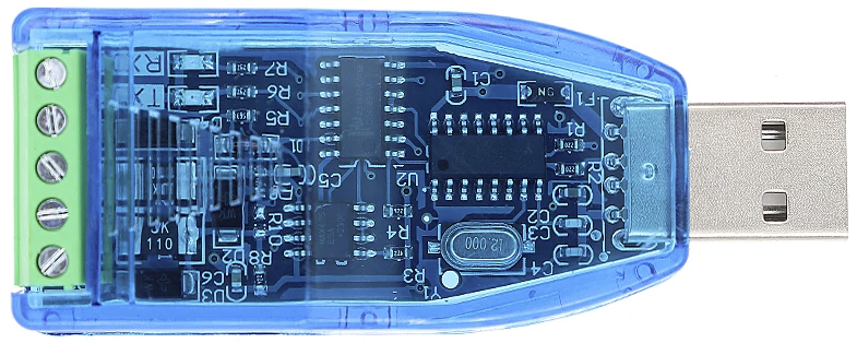
The Industrial USB to RS485 is a versatile converter that bridges USB devices with RS485 serial devices. It enables seamless data transmission over long distances, making it ideal for industrial environments where robust and reliable communication is essential. This component is widely used in applications such as industrial automation, building management systems, and data acquisition systems. Its plug-and-play functionality and compatibility with various operating systems make it a convenient solution for modern industrial communication needs.

Explore Projects Built with Industrial USB To RS485

Use Cirkit Designer to design, explore, and prototype these projects online. Some projects support real-time simulation. Click "Open Project" to start designing instantly!
STM32 and Arduino UNO Based Dual RS485 Communication Interface
Image of STM to Arduino RS485: A project utilizing Industrial USB To RS485 in a practical application
This circuit consists of two microcontrollers, an STM32F103C8T6 and an Arduino UNO, each interfaced with separate RS485 transceiver modules for serial communication. The STM32F103C8T6 controls the RE (Receiver Enable) and DE (Driver Enable) pins of one RS485 module to manage its operation, and communicates via the A9 and A10 pins for DI (Data Input) and RO (Receiver Output), respectively. The Arduino UNO is similarly connected to another RS485 module, with digital pins D2 and D3 interfacing with DI and RO, and D8 controlling both RE and DE. The RS485 modules are connected to each other through their A and B differential communication lines, enabling serial data exchange between the two microcontrollers over a robust and long-distance capable RS485 network.
Cirkit Designer LogoOpen Project in Cirkit Designer
Arduino UNO and Relay-Controlled RS485 Communication System
Image of Diagrama: A project utilizing Industrial USB To RS485 in a practical application
This circuit features an Arduino UNO microcontroller interfaced with a 4-channel relay module and a UART TTL to RS485 converter. The Arduino controls the relays via digital pins and communicates with the RS485 converter for serial communication, enabling control of external devices and communication over long distances.
Cirkit Designer LogoOpen Project in Cirkit Designer
Arduino UNO Based RS-485 Communication System with Pushbutton Activation and LED Indicator
Image of tp: A project utilizing Industrial USB To RS485 in a practical application
This circuit consists of two Arduino UNO microcontrollers interfaced with RS-485 modules to enable serial communication over a differential bus, allowing for robust long-distance data transmission. One Arduino is configured as a master, sending a message when a pushbutton is pressed, while the other Arduino is set up as a slave, responding by lighting up an LED when the correct message is received. The system is powered by two separate 9V batteries, and a resistor is used to limit the current through the LED.
Cirkit Designer LogoOpen Project in Cirkit Designer
Arduino Nano-Based RS485 Communication Interface with LED Indicators
Image of RS485: A project utilizing Industrial USB To RS485 in a practical application
This circuit is designed for serial communication between two Arduino Nano microcontrollers and a computer, using RS485 transceivers for differential signaling. Each Arduino also interfaces with a trimmer potentiometer for analog input and controls an LED, indicating status or providing user feedback.
Cirkit Designer LogoOpen Project in Cirkit Designer

Explore Projects Built with Industrial USB To RS485

Use Cirkit Designer to design, explore, and prototype these projects online. Some projects support real-time simulation. Click "Open Project" to start designing instantly!
Image of STM to Arduino RS485: A project utilizing Industrial USB To RS485 in a practical application
STM32 and Arduino UNO Based Dual RS485 Communication Interface
This circuit consists of two microcontrollers, an STM32F103C8T6 and an Arduino UNO, each interfaced with separate RS485 transceiver modules for serial communication. The STM32F103C8T6 controls the RE (Receiver Enable) and DE (Driver Enable) pins of one RS485 module to manage its operation, and communicates via the A9 and A10 pins for DI (Data Input) and RO (Receiver Output), respectively. The Arduino UNO is similarly connected to another RS485 module, with digital pins D2 and D3 interfacing with DI and RO, and D8 controlling both RE and DE. The RS485 modules are connected to each other through their A and B differential communication lines, enabling serial data exchange between the two microcontrollers over a robust and long-distance capable RS485 network.
Cirkit Designer LogoOpen Project in Cirkit Designer
Image of Diagrama: A project utilizing Industrial USB To RS485 in a practical application
Arduino UNO and Relay-Controlled RS485 Communication System
This circuit features an Arduino UNO microcontroller interfaced with a 4-channel relay module and a UART TTL to RS485 converter. The Arduino controls the relays via digital pins and communicates with the RS485 converter for serial communication, enabling control of external devices and communication over long distances.
Cirkit Designer LogoOpen Project in Cirkit Designer
Image of tp: A project utilizing Industrial USB To RS485 in a practical application
Arduino UNO Based RS-485 Communication System with Pushbutton Activation and LED Indicator
This circuit consists of two Arduino UNO microcontrollers interfaced with RS-485 modules to enable serial communication over a differential bus, allowing for robust long-distance data transmission. One Arduino is configured as a master, sending a message when a pushbutton is pressed, while the other Arduino is set up as a slave, responding by lighting up an LED when the correct message is received. The system is powered by two separate 9V batteries, and a resistor is used to limit the current through the LED.
Cirkit Designer LogoOpen Project in Cirkit Designer
Image of RS485: A project utilizing Industrial USB To RS485 in a practical application
Arduino Nano-Based RS485 Communication Interface with LED Indicators
This circuit is designed for serial communication between two Arduino Nano microcontrollers and a computer, using RS485 transceivers for differential signaling. Each Arduino also interfaces with a trimmer potentiometer for analog input and controls an LED, indicating status or providing user feedback.
Cirkit Designer LogoOpen Project in Cirkit Designer

Technical Specifications

  • Communication Standard: USB 2.0 to RS485
  • Baud Rate: 300 bps to 3 Mbps
  • Operating Voltage: 5V (powered via USB)
  • Operating Temperature: -40°C to 85°C
  • Maximum Communication Distance: Up to 1200 meters (depending on cable quality and baud rate)
  • Protection Features:
    • Built-in surge protection
    • ESD (Electrostatic Discharge) protection
  • Connector Types: USB Type-A (input) and terminal block or DB9 (RS485 output)
  • Driver Support: Compatible with Windows, macOS, and Linux

Pin Configuration and Descriptions

RS485 Terminal Block Pinout

Pin Name Description
A (D+) RS485 Data Line Positive (non-inverting)
B (D-) RS485 Data Line Negative (inverting)
GND Ground Reference

USB Connector Pinout (Type-A)

Pin Name Description
VBUS +5V Power Supply
D+ USB Data Positive
D- USB Data Negative
GND Ground Reference

Usage Instructions

How to Use the Component in a Circuit

  1. Connect the USB Port: Plug the USB Type-A connector into your computer or USB host device. Ensure the necessary drivers are installed (most operating systems will install them automatically).
  2. Connect the RS485 Device:
    • Use the terminal block or DB9 connector to connect the RS485 device.
    • Match the RS485 device's A (D+) and B (D-) lines to the corresponding pins on the converter.
  3. Power and Communication: The converter is powered via the USB port. Once connected, it will enable communication between the USB host and the RS485 device.

Important Considerations and Best Practices

  • Cable Quality: Use high-quality twisted-pair cables for RS485 connections to minimize signal degradation over long distances.
  • Termination Resistors: For long-distance communication, ensure proper termination resistors (typically 120 ohms) are installed at both ends of the RS485 bus to prevent signal reflections.
  • Grounding: Ensure a common ground between the USB to RS485 converter and the RS485 device to avoid communication errors.
  • Device Addressing: If multiple RS485 devices are connected on the same bus, ensure each device has a unique address to avoid conflicts.

Example Code for Arduino UNO

The Industrial USB to RS485 converter can be used with an Arduino UNO to communicate with RS485 devices. Below is an example of how to send and receive data using the SoftwareSerial library.

#include <SoftwareSerial.h>

// Define RS485 pins for communication
#define RX_PIN 10  // Arduino pin connected to RS485 RX
#define TX_PIN 11  // Arduino pin connected to RS485 TX
#define DE_PIN 9   // Arduino pin for Driver Enable (DE) control

SoftwareSerial RS485Serial(RX_PIN, TX_PIN);

void setup() {
  pinMode(DE_PIN, OUTPUT);  // Set DE pin as output
  digitalWrite(DE_PIN, LOW); // Set DE to LOW (receive mode)
  
  Serial.begin(9600);       // Initialize Serial Monitor
  RS485Serial.begin(9600);  // Initialize RS485 communication
  
  Serial.println("RS485 Communication Initialized");
}

void loop() {
  // Send data to RS485 device
  digitalWrite(DE_PIN, HIGH); // Enable transmit mode
  RS485Serial.println("Hello RS485 Device!");
  digitalWrite(DE_PIN, LOW);  // Enable receive mode
  
  delay(1000); // Wait for a second
  
  // Receive data from RS485 device
  if (RS485Serial.available()) {
    String receivedData = RS485Serial.readString();
    Serial.print("Received: ");
    Serial.println(receivedData);
  }
}

Notes:

  • Connect the DE (Driver Enable) pin to control the RS485 transceiver's transmit and receive modes.
  • Adjust the baud rate in the code to match the RS485 device's communication settings.

Troubleshooting and FAQs

Common Issues

  1. No Communication Between Devices

    • Cause: Incorrect wiring or mismatched baud rates.
    • Solution: Double-check the wiring and ensure the baud rate settings match on both devices.
  2. Data Corruption Over Long Distances

    • Cause: Signal degradation or lack of termination resistors.
    • Solution: Use high-quality cables and install 120-ohm termination resistors at both ends of the RS485 bus.
  3. Device Not Recognized by Computer

    • Cause: Missing or outdated USB drivers.
    • Solution: Install the latest drivers from the manufacturer's website or allow the operating system to update them automatically.
  4. Interference in Communication

    • Cause: Electrical noise in the environment.
    • Solution: Use shielded cables and ensure proper grounding.

FAQs

  • Q: Can I connect multiple RS485 devices to this converter?

    • A: Yes, RS485 supports multi-drop communication. Ensure each device has a unique address.
  • Q: What is the maximum cable length supported?

    • A: The maximum length is 1200 meters, but this depends on the cable quality and baud rate.
  • Q: Do I need external power for the converter?

    • A: No, the converter is powered via the USB port.
  • Q: Is this converter compatible with macOS and Linux?

    • A: Yes, it is compatible with Windows, macOS, and Linux operating systems.