Cirkit Designer Logo
Cirkit Designer
Your all-in-one circuit design IDE
Home / 
Component Documentation

How to Use 5v 2-Relay JD-VCC: Examples, Pinouts, and Specs

Image of 5v 2-Relay JD-VCC
Cirkit Designer LogoDesign with 5v 2-Relay JD-VCC in Cirkit Designer

Introduction

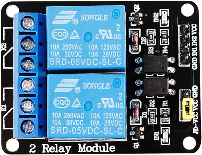
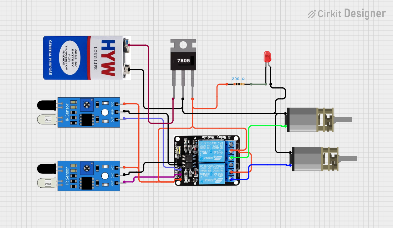
The 5V 2-Relay Module with JD-VCC power supply input is an electronic device used to control high voltage/current loads. It allows a low-power signal from a microcontroller, such as an Arduino, to control larger power circuits. This module is commonly used in automation projects, home appliances control, and in switching devices on and off.

Explore Projects Built with 5v 2-Relay JD-VCC

Use Cirkit Designer to design, explore, and prototype these projects online. Some projects support real-time simulation. Click "Open Project" to start designing instantly!
DC-DC Converter and Relay Module Power Distribution System
Image of relay: A project utilizing 5v 2-Relay JD-VCC in a practical application
This circuit consists of a DC-DC converter powering a 6-channel power module, which in turn supplies 5V to a 2-relay module. The power module distributes the converted voltage to the relay module, enabling it to control external devices.
Cirkit Designer LogoOpen Project in Cirkit Designer
WeMos D1 R2 Controlled Relay Switching Circuit for AC Bulb and USB Charger
Image of Hand Gesture Light: A project utilizing 5v 2-Relay JD-VCC in a practical application
This circuit uses a WeMos D1 R2 microcontroller to control a 5V 2-relay module, which in turn controls the power to an AC bulb and a cellphone charger. The microcontroller also interfaces with a line tracking sensor, which likely provides input to control the relay states. The AC bulb and cellphone charger are powered by an AC wire connection, with the relay acting as a switch for the bulb.
Cirkit Designer LogoOpen Project in Cirkit Designer
IR Sensor-Controlled Dual Motor System with Relay and LED Indicator
Image of LINE FOLLOWER: A project utilizing 5v 2-Relay JD-VCC in a practical application
This circuit uses two IR sensors to control a 5V relay module, which in turn drives two DC motors. A 7805 voltage regulator is used to step down the voltage from a 9V battery to 5V, powering the sensors and relay. An LED with a current-limiting resistor indicates the power status.
Cirkit Designer LogoOpen Project in Cirkit Designer
ESP32-Powered 8-Channel Relay Controller with Wi-Fi Connectivity
Image of Olimex ESP32-POE2 4Ch X 2 Switches: A project utilizing 5v 2-Relay JD-VCC in a practical application
This circuit features an ESP32 microcontroller connected to an 8-channel relay module. The ESP32 controls the relay channels via its GPIO pins, allowing for the switching of external devices or loads through the relays.
Cirkit Designer LogoOpen Project in Cirkit Designer

Explore Projects Built with 5v 2-Relay JD-VCC

Use Cirkit Designer to design, explore, and prototype these projects online. Some projects support real-time simulation. Click "Open Project" to start designing instantly!
Image of relay: A project utilizing 5v 2-Relay JD-VCC in a practical application
DC-DC Converter and Relay Module Power Distribution System
This circuit consists of a DC-DC converter powering a 6-channel power module, which in turn supplies 5V to a 2-relay module. The power module distributes the converted voltage to the relay module, enabling it to control external devices.
Cirkit Designer LogoOpen Project in Cirkit Designer
Image of Hand Gesture Light: A project utilizing 5v 2-Relay JD-VCC in a practical application
WeMos D1 R2 Controlled Relay Switching Circuit for AC Bulb and USB Charger
This circuit uses a WeMos D1 R2 microcontroller to control a 5V 2-relay module, which in turn controls the power to an AC bulb and a cellphone charger. The microcontroller also interfaces with a line tracking sensor, which likely provides input to control the relay states. The AC bulb and cellphone charger are powered by an AC wire connection, with the relay acting as a switch for the bulb.
Cirkit Designer LogoOpen Project in Cirkit Designer
Image of LINE FOLLOWER: A project utilizing 5v 2-Relay JD-VCC in a practical application
IR Sensor-Controlled Dual Motor System with Relay and LED Indicator
This circuit uses two IR sensors to control a 5V relay module, which in turn drives two DC motors. A 7805 voltage regulator is used to step down the voltage from a 9V battery to 5V, powering the sensors and relay. An LED with a current-limiting resistor indicates the power status.
Cirkit Designer LogoOpen Project in Cirkit Designer
Image of Olimex ESP32-POE2 4Ch X 2 Switches: A project utilizing 5v 2-Relay JD-VCC in a practical application
ESP32-Powered 8-Channel Relay Controller with Wi-Fi Connectivity
This circuit features an ESP32 microcontroller connected to an 8-channel relay module. The ESP32 controls the relay channels via its GPIO pins, allowing for the switching of external devices or loads through the relays.
Cirkit Designer LogoOpen Project in Cirkit Designer

Common Applications and Use Cases

  • Home automation systems
  • Industrial controls
  • Automotive electronics
  • Remote controlled switches

Technical Specifications

Key Technical Details

  • Operating Voltage (VCC): 5V
  • Relay Power Supply (JD-VCC): 4.5V to 5.5V
  • Current Consumption: Approx. 70mA per relay
  • Maximum Switching Voltage: 250VAC / 30VDC
  • Maximum Switching Current: 10A (AC) / 10A (DC)
  • Control Signal Voltage: 0V - 0.5V (LOW), 2.5V - 5V (HIGH)
  • Control Signal Current: 2mA - 20mA

Pin Configuration and Descriptions

Pin Name Description
JD-VCC Relay power supply input (4.5V to 5.5V)
VCC Module power supply input (5V)
GND Ground connection
IN1 Control signal input for Relay 1
IN2 Control signal input for Relay 2
NO1 Normally Open contact for Relay 1
COM1 Common contact for Relay 1
NC1 Normally Closed contact for Relay 1
NO2 Normally Open contact for Relay 2
COM2 Common contact for Relay 2
NC2 Normally Closed contact for Relay 2

Usage Instructions

How to Use the Component in a Circuit

  1. Power Connections:

    • Connect the JD-VCC pin to an external 5V power supply if isolation between the relay power and control signal is needed.
    • Connect the VCC pin to the 5V output of the microcontroller if isolation is not required.
    • Connect the GND pin to the ground of the power supply and microcontroller.
  2. Control Signal:

    • Connect IN1 and IN2 to digital output pins on the microcontroller to control Relay 1 and Relay 2, respectively.
  3. Load Connections:

    • Connect the device you want to control to the NO (Normally Open) or NC (Normally Closed) and COM (Common) pins of the relay.

Important Considerations and Best Practices

  • Ensure that the power supply for JD-VCC is capable of delivering sufficient current for the number of relays being used.
  • Do not exceed the maximum voltage/current ratings of the relays to prevent damage.
  • Use flyback diodes when controlling inductive loads to prevent back EMF damage.
  • Always ensure proper isolation between the low voltage control circuit and high voltage load circuit for safety.

Example Code for Arduino UNO

// Define relay control pins
#define RELAY1_PIN  7
#define RELAY2_PIN  8

void setup() {
  // Set relay pins as outputs
  pinMode(RELAY1_PIN, OUTPUT);
  pinMode(RELAY2_PIN, OUTPUT);
}

void loop() {
  // Turn Relay 1 ON
  digitalWrite(RELAY1_PIN, LOW); // Assumes active LOW relays
  delay(1000); // Wait for 1 second
  
  // Turn Relay 1 OFF
  digitalWrite(RELAY1_PIN, HIGH);
  delay(1000); // Wait for 1 second
  
  // Turn Relay 2 ON
  digitalWrite(RELAY2_PIN, LOW);
  delay(1000); // Wait for 1 second
  
  // Turn Relay 2 OFF
  digitalWrite(RELAY2_PIN, HIGH);
  delay(1000); // Wait for 1 second
}

Troubleshooting and FAQs

Common Issues Users Might Face

  • Relay not activating: Check the control signal voltage and connections.
  • Intermittent operation: Ensure that the power supply is stable and can provide enough current.
  • Clicking sound but no switching: Verify the load does not exceed the relay's maximum ratings.

Solutions and Tips for Troubleshooting

  • Double-check wiring, especially the power supply to JD-VCC, VCC, and ground connections.
  • Use a multimeter to check the control signal voltage at IN1 and IN2.
  • Ensure that the microcontroller's digital output pins are configured correctly.

FAQs

Q: Can I power the module using the same 5V from the Arduino? A: Yes, you can power the module using the 5V from the Arduino if isolation between the relay power and control signal is not required.

Q: What does JD-VCC stand for? A: JD-VCC refers to the relay power supply input, which can be used to separate the relay power from the control logic power.

Q: Can I control AC and DC loads with this relay module? A: Yes, the relay module can switch both AC and DC loads within its specified voltage and current ratings.