How to Use KWH meter: Examples, Pinouts, and Specs
Introduction
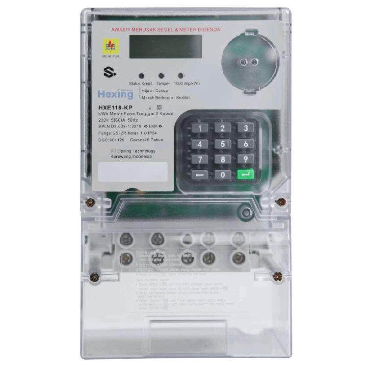
A KWH meter, also known as an energy meter, measures the amount of electrical energy consumed by a residence, business, or an electrically powered device. It records energy usage in kilowatt-hours (KWH), which is a standard unit of energy. This measurement is essential for billing purposes, energy monitoring, and efficient power management.
Explore Projects Built with KWH meter

Explore Projects Built with KWH meter
Common Applications and Use Cases
- Residential electricity consumption monitoring for utility billing.
- Industrial and commercial energy usage tracking.
- Integration into smart home systems for real-time energy monitoring.
- Energy audits and efficiency analysis.
- Renewable energy systems to measure energy production and consumption.
Technical Specifications
Below are the general technical specifications for a typical KWH meter. Note that specific models may vary slightly in their ratings and features.
| Parameter | Specification |
|---|---|
| Voltage Rating | 110V - 240V AC |
| Current Rating | 5A - 100A (varies by model) |
| Frequency | 50Hz / 60Hz |
| Accuracy Class | Class 1.0 or Class 2.0 |
| Power Consumption | ≤ 2W / 10VA |
| Measurement Range | 0 - 99999.9 kWh |
| Display Type | LCD or LED |
| Communication Interface | RS485, Modbus, or wireless (optional) |
| Operating Temperature | -20°C to +60°C |
| Storage Temperature | -25°C to +70°C |
| Humidity | ≤ 95% (non-condensing) |
Pin Configuration and Descriptions
The pin configuration for a KWH meter typically includes terminals for power input, load connection, and communication. Below is a general example:
| Pin Number | Label | Description |
|---|---|---|
| 1 | L (Line) | Live wire input for power supply. |
| 2 | N (Neutral) | Neutral wire input for power supply. |
| 3 | L (Load Line) | Live wire output to the load. |
| 4 | N (Load Neutral) | Neutral wire output to the load. |
| 5 | RS485 A | RS485 communication line A (optional). |
| 6 | RS485 B | RS485 communication line B (optional). |
Usage Instructions
How to Use the Component in a Circuit
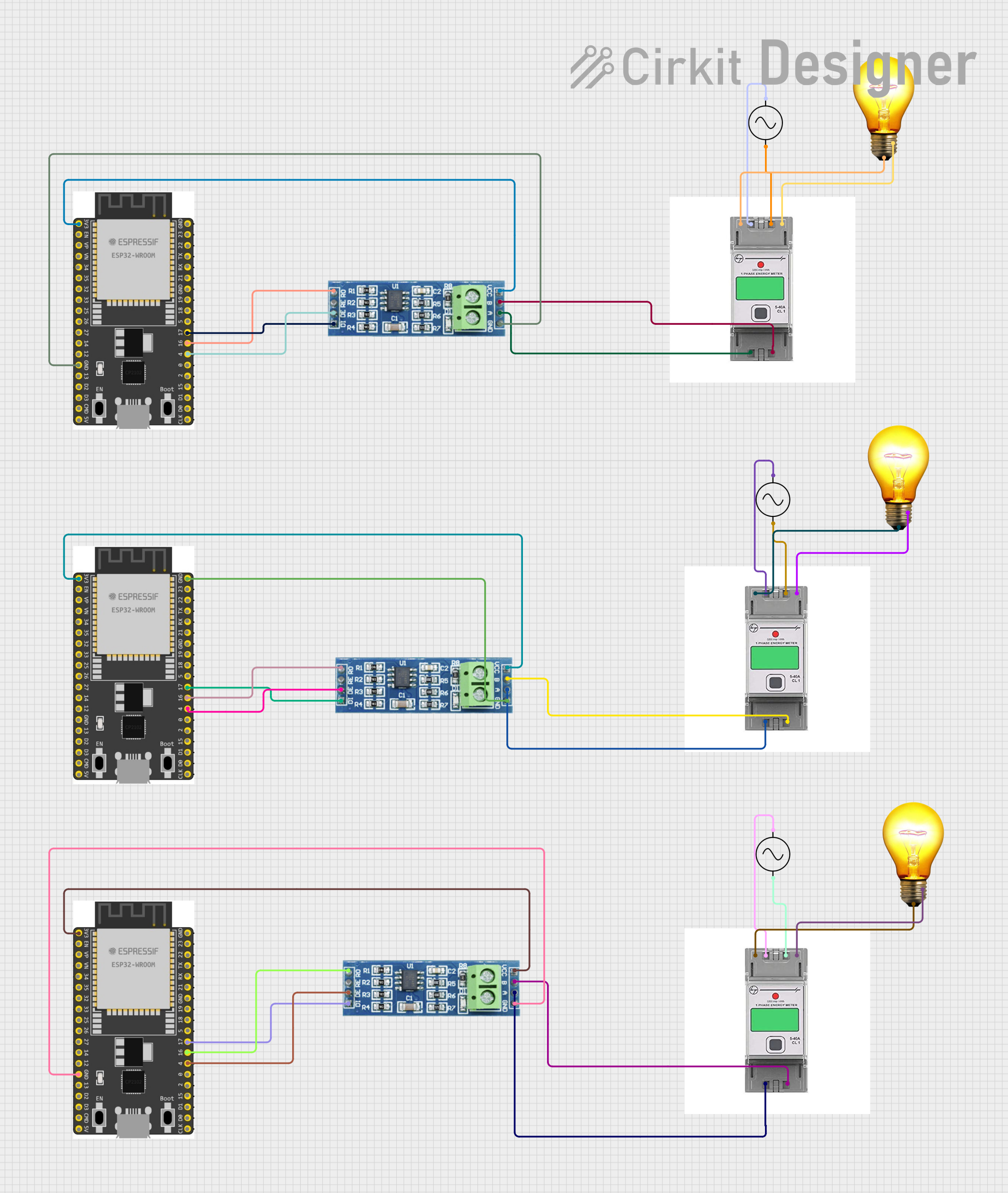
Wiring the KWH Meter:
- Connect the live (L) and neutral (N) wires from the power source to the input terminals of the KWH meter.
- Connect the live (L) and neutral (N) wires from the load to the output terminals of the KWH meter.
- If the meter supports communication (e.g., RS485), connect the communication lines (A and B) to the appropriate interface.
Powering On:
- Once the wiring is complete, turn on the power supply. The meter's display should activate, showing the current energy consumption and other parameters.
Reading the Display:
- The display typically shows the total energy consumed in KWH, along with other data such as voltage, current, and power factor (depending on the model).
Optional Communication:
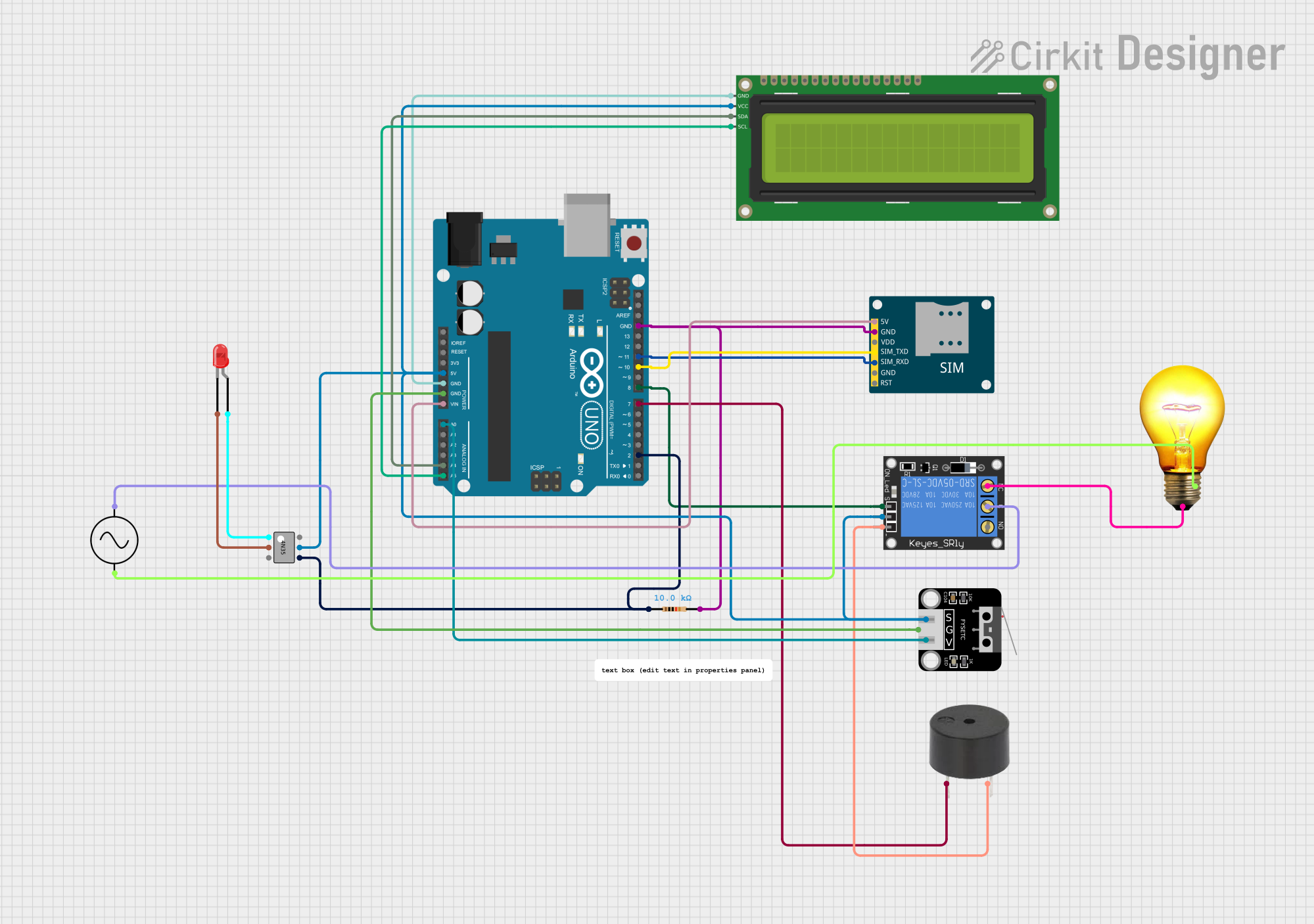
- If the meter supports RS485 or Modbus communication, connect it to a microcontroller or computer for remote monitoring and data logging.
Important Considerations and Best Practices
- Ensure the meter's voltage and current ratings match the application to avoid damage.
- Use proper insulation and secure connections to prevent electrical hazards.
- Avoid exposing the meter to extreme temperatures or moisture.
- If integrating with a microcontroller (e.g., Arduino), ensure the communication protocol (e.g., RS485) is correctly implemented.
Example: Connecting a KWH Meter to an Arduino UNO
If your KWH meter supports RS485 communication, you can use an RS485-to-TTL module to interface it with an Arduino UNO. Below is an example code snippet to read data from the meter:
#include <ModbusMaster.h>

// Create an instance of the ModbusMaster library
ModbusMaster node;

// Define the RS485 communication pins
#define RE_DE_PIN 2  // Pin to control RS485 module (RE/DE)

// Function to control RS485 module direction
void preTransmission() {
  digitalWrite(RE_DE_PIN, HIGH); // Enable transmission mode
}

void postTransmission() {
  digitalWrite(RE_DE_PIN, LOW);  // Enable reception mode
}

void setup() {
  // Initialize serial communication
  Serial.begin(9600);
  Serial.println("KWH Meter Reading");

  // Initialize RS485 control pin
  pinMode(RE_DE_PIN, OUTPUT);
  digitalWrite(RE_DE_PIN, LOW);

  // Initialize Modbus communication
  node.begin(1, Serial); // Set Modbus ID to 1
  node.preTransmission(preTransmission);
  node.postTransmission(postTransmission);
}

void loop() {
  uint8_t result;
  uint16_t data[2];

  // Read energy consumption (e.g., register 0x0000)
  result = node.readInputRegisters(0x0000, 2);

  if (result == node.ku8MBSuccess) {
    // Combine two 16-bit registers into a 32-bit value
    uint32_t energy = (data[0] << 16) | data[1];
    Serial.print("Energy Consumption: ");
    Serial.print(energy);
    Serial.println(" kWh");
  } else {
    Serial.println("Failed to read data from KWH meter.");
  }

  delay(1000); // Wait 1 second before the next reading
}
Notes:
- Replace
0x0000with the correct register address for energy consumption as per your meter's datasheet. - Ensure the baud rate and Modbus ID match the meter's configuration.
Troubleshooting and FAQs
Common Issues Users Might Face
No Display or Power:
- Cause: Incorrect wiring or no power supply.
- Solution: Verify the live and neutral connections and ensure the power source is active.
Incorrect Readings:
- Cause: Overloading the meter or incorrect calibration.
- Solution: Ensure the load is within the meter's rated capacity. Check calibration settings.
Communication Failure:
- Cause: Incorrect RS485 wiring or mismatched settings.
- Solution: Verify the A and B lines are correctly connected. Check baud rate and Modbus ID.
Meter Overheating:
- Cause: Prolonged operation at maximum load.
- Solution: Reduce the load or use a meter with a higher current rating.
Solutions and Tips for Troubleshooting
- Always refer to the meter's datasheet for specific wiring and configuration details.
- Use a multimeter to verify voltage and current levels at the input and output terminals.
- For communication issues, use a protocol analyzer to debug RS485 or Modbus signals.
By following this documentation, you can effectively use a KWH meter for energy monitoring and management in various applications.