Cirkit Designer Logo
Cirkit Designer
Your all-in-one circuit design IDE
Home / 
Component Documentation

How to Use UPS 5V: Examples, Pinouts, and Specs

Image of UPS 5V
Cirkit Designer LogoDesign with UPS 5V in Cirkit Designer

Introduction

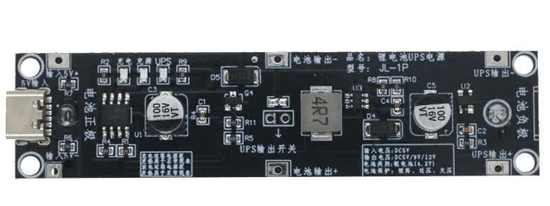
The UPS 5V by 18650 is a compact and reliable Uninterruptible Power Supply designed to deliver a stable 5V output. It ensures uninterrupted power to connected devices during power outages or voltage fluctuations, making it ideal for critical applications where consistent power is essential. This component is particularly useful for microcontrollers, IoT devices, Raspberry Pi, and other low-power electronics.

Explore Projects Built with UPS 5V

Use Cirkit Designer to design, explore, and prototype these projects online. Some projects support real-time simulation. Click "Open Project" to start designing instantly!
12V UPS System with Dual 18650 Li-ion Battery Backup and Voltage Regulation
Image of Power supply: A project utilizing UPS 5V in a practical application
This circuit is designed to provide an uninterruptible power supply (UPS) system with a 12V DC output. It includes a 12V 5A power supply connected to an AC source through a toggle switch, which charges a pair of 18650 Li-ion batteries via a voltage regulator (XL4016). The UPS module ensures a continuous power supply to the load by switching between the power supply and the battery bank.
Cirkit Designer LogoOpen Project in Cirkit Designer
Solar-Powered UPS with Dual Step-Down Converters and ESP32 Control
Image of My Schematic 2: A project utilizing UPS 5V in a practical application
This circuit is designed to provide a stable power supply from various sources. It integrates a solar panel with a solar charge controller to charge a 12V battery, which is then connected to a UPS module for regulated output. The circuit also includes two 12v to 5v step-down power converters to supply 5V power, one of which powers an ESP32 Devkit V1 microcontroller, and a switching power supply to provide an alternative AC to DC conversion input to the UPS module.
Cirkit Designer LogoOpen Project in Cirkit Designer
Battery-Powered UPS with Step-Down Buck Converter and BMS
Image of Mini ups: A project utilizing UPS 5V in a practical application
This circuit is a power management system that steps down a 240V AC input to a lower DC voltage using a buck converter, which then powers a 40W UPS. The UPS is controlled by a rocker switch and is backed up by a battery management system (BMS) connected to three 3.7V batteries in series, ensuring continuous power supply.
Cirkit Designer LogoOpen Project in Cirkit Designer
ESP32-S3 Battery-Powered Environmental Monitoring System with OLED Display
Image of Diagram wiring: A project utilizing UPS 5V in a practical application
This circuit is a sensor and display system powered by a UPS module with a 12V power supply and 18650 batteries. It includes an ESP32 microcontroller that interfaces with various sensors (DHT22, Strain Gauge, MPU-6050, ADXL345) and an OLED display, with power regulation provided by a step-down buck converter.
Cirkit Designer LogoOpen Project in Cirkit Designer

Explore Projects Built with UPS 5V

Use Cirkit Designer to design, explore, and prototype these projects online. Some projects support real-time simulation. Click "Open Project" to start designing instantly!
Image of Power supply: A project utilizing UPS 5V in a practical application
12V UPS System with Dual 18650 Li-ion Battery Backup and Voltage Regulation
This circuit is designed to provide an uninterruptible power supply (UPS) system with a 12V DC output. It includes a 12V 5A power supply connected to an AC source through a toggle switch, which charges a pair of 18650 Li-ion batteries via a voltage regulator (XL4016). The UPS module ensures a continuous power supply to the load by switching between the power supply and the battery bank.
Cirkit Designer LogoOpen Project in Cirkit Designer
Image of My Schematic 2: A project utilizing UPS 5V in a practical application
Solar-Powered UPS with Dual Step-Down Converters and ESP32 Control
This circuit is designed to provide a stable power supply from various sources. It integrates a solar panel with a solar charge controller to charge a 12V battery, which is then connected to a UPS module for regulated output. The circuit also includes two 12v to 5v step-down power converters to supply 5V power, one of which powers an ESP32 Devkit V1 microcontroller, and a switching power supply to provide an alternative AC to DC conversion input to the UPS module.
Cirkit Designer LogoOpen Project in Cirkit Designer
Image of Mini ups: A project utilizing UPS 5V in a practical application
Battery-Powered UPS with Step-Down Buck Converter and BMS
This circuit is a power management system that steps down a 240V AC input to a lower DC voltage using a buck converter, which then powers a 40W UPS. The UPS is controlled by a rocker switch and is backed up by a battery management system (BMS) connected to three 3.7V batteries in series, ensuring continuous power supply.
Cirkit Designer LogoOpen Project in Cirkit Designer
Image of Diagram wiring: A project utilizing UPS 5V in a practical application
ESP32-S3 Battery-Powered Environmental Monitoring System with OLED Display
This circuit is a sensor and display system powered by a UPS module with a 12V power supply and 18650 batteries. It includes an ESP32 microcontroller that interfaces with various sensors (DHT22, Strain Gauge, MPU-6050, ADXL345) and an OLED display, with power regulation provided by a step-down buck converter.
Cirkit Designer LogoOpen Project in Cirkit Designer

Common Applications and Use Cases

  • Power backup for Raspberry Pi, Arduino, and other microcontrollers.
  • IoT devices requiring stable power during outages.
  • Portable electronics and battery-powered systems.
  • Emergency power supply for small sensors and modules.
  • Preventing data loss in devices during sudden power cuts.

Technical Specifications

The following table outlines the key technical details of the UPS 5V:

Parameter Value
Input Voltage 5V DC
Output Voltage 5V DC (regulated)
Output Current Up to 2A
Battery Type 18650 Lithium-Ion (not included)
Charging Voltage 5V DC
Charging Current 1A (max)
Protection Features Overcharge, Overdischarge, Short Circuit
Dimensions 60mm x 30mm x 15mm

Pin Configuration and Descriptions

The UPS 5V module typically includes the following pins and connectors:

Pin/Connector Description
VIN Input voltage (5V DC) for charging the battery.
VOUT Regulated 5V output to power connected devices.
GND Ground connection for input and output.
Battery Holder Slot for a single 18650 Lithium-Ion battery.
USB Port (Optional) USB output for powering USB devices.

Usage Instructions

How to Use the UPS 5V in a Circuit

  1. Insert the Battery: Place a fully charged 18650 Lithium-Ion battery into the battery holder, ensuring correct polarity.
  2. Connect Input Power: Supply 5V DC to the VIN pin or micro-USB input to charge the battery and power the module.
  3. Connect Output Load: Attach your device to the VOUT pin or USB output. The module will provide a stable 5V output.
  4. Automatic Switching: During a power outage, the module will automatically switch to battery power without interrupting the output.

Important Considerations and Best Practices

  • Use a high-quality 18650 battery with built-in protection for safety.
  • Ensure the input voltage does not exceed 5V to avoid damaging the module.
  • Avoid short-circuiting the output pins to prevent module failure.
  • Do not exceed the maximum output current of 2A to maintain stable operation.
  • For long-term use, periodically check the battery's health and replace it if necessary.

Example: Using UPS 5V with Arduino UNO

The UPS 5V can be used to power an Arduino UNO during power outages. Below is an example setup and code:

Circuit Setup

  1. Connect the VOUT pin of the UPS 5V to the 5V pin of the Arduino UNO.
  2. Connect the GND pin of the UPS 5V to the GND pin of the Arduino UNO.
  3. Optionally, connect sensors or modules to the Arduino as needed.

Arduino Code Example

// Example code to demonstrate a simple LED blink program
// This ensures the Arduino remains operational during power outages.

const int ledPin = 13; // Built-in LED pin on Arduino UNO

void setup() {
  pinMode(ledPin, OUTPUT); // Set the LED pin as an output
}

void loop() {
  digitalWrite(ledPin, HIGH); // Turn the LED on
  delay(1000);                // Wait for 1 second
  digitalWrite(ledPin, LOW);  // Turn the LED off
  delay(1000);                // Wait for 1 second
}

Troubleshooting and FAQs

Common Issues and Solutions

Issue Solution
No output voltage when power is disconnected Ensure the battery is properly inserted and charged.
Output voltage is unstable Check if the load exceeds the 2A maximum current rating.
Module overheats during operation Verify that the input voltage is 5V and the battery is in good condition.
Battery does not charge Ensure the input power source provides sufficient current (at least 1A).

FAQs

  1. Can I use a different type of battery?
    No, the module is designed specifically for 18650 Lithium-Ion batteries.

  2. What happens if the battery is over-discharged?
    The module includes overdischarge protection to prevent damage to the battery.

  3. Can I power multiple devices simultaneously?
    Yes, as long as the total current draw does not exceed 2A.

  4. Is the UPS 5V suitable for outdoor use?
    The module is not weatherproof. Use it in a dry, indoor environment or enclose it in a protective case for outdoor use.

By following this documentation, you can effectively integrate the UPS 5V into your projects and ensure reliable power delivery during outages or fluctuations.