How to Use 1 Channel Way Optocoupler Isolation Module PC817 EL817 12V: Examples, Pinouts, and Specs
Introduction
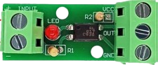
The 1 Channel Way Optocoupler Isolation Module PC817 EL817 12V, manufactured by AC (Part ID: Optocoupler), is an electronic module designed to provide electrical isolation between its input and output. It uses the PC817 or EL817 optocoupler to transmit signals while preventing direct electrical connection, ensuring safety and protecting sensitive components from high-voltage circuits.
This module is widely used in applications requiring signal isolation, such as:
- Interfacing microcontrollers with high-voltage circuits.
- Protecting low-voltage devices from voltage spikes or surges.
- Signal level shifting and noise suppression in industrial control systems.
- Isolated communication between different circuit domains.
Explore Projects Built with 1 Channel Way Optocoupler Isolation Module PC817 EL817 12V


Explore Projects Built with 1 Channel Way Optocoupler Isolation Module PC817 EL817 12V
Technical Specifications
Below are the key technical details of the module:
| Parameter | Value |
|---|---|
| Operating Voltage | 12V DC |
| Optocoupler Model | PC817 or EL817 |
| Input Signal Voltage | 3.3V to 12V |
| Output Signal Voltage | 0V to 12V (depending on load) |
| Isolation Voltage | 5,000V (typical for PC817) |
| Input Current | 5mA to 20mA |
| Output Type | Open-collector |
| Dimensions | 25mm x 15mm x 10mm |
Pin Configuration and Descriptions
The module has a simple pinout for easy integration into circuits:
| Pin | Name | Description |
|---|---|---|
| 1 | VCC | Positive power supply input (12V DC). |
| 2 | GND | Ground connection for the module. |
| 3 | Signal Input | Input pin for the signal to be isolated. Accepts 3.3V to 12V logic levels. |
| 4 | Signal Output | Isolated output pin. Open-collector output; requires a pull-up resistor. |
Usage Instructions
How to Use the Module in a Circuit
- Power the Module: Connect the
VCCpin to a 12V DC power supply and theGNDpin to the ground of the same power source. - Input Signal: Connect the signal source (e.g., a microcontroller GPIO pin) to the
Signal Inputpin. Ensure the input voltage is within the range of 3.3V to 12V. - Output Signal: Connect the
Signal Outputpin to the target circuit. Since the output is open-collector, you must use a pull-up resistor (e.g., 10kΩ) to the desired output voltage level. - Load Connection: The output can drive low-current loads directly or act as a control signal for other components like transistors or relays.
Important Considerations and Best Practices
- Pull-Up Resistor: Always use a pull-up resistor on the
Signal Outputpin to ensure proper operation. The resistor value depends on the desired output voltage and current requirements. - Input Current Limiting: The input side of the optocoupler requires a current-limiting resistor to prevent excessive current through the LED inside the optocoupler. This is typically pre-installed on the module.
- Isolation Voltage: Ensure the isolation voltage rating (5,000V) is not exceeded to maintain safe operation.
- Signal Polarity: The input signal is active-high, meaning the LED inside the optocoupler is activated when the input signal is high.
Example: Connecting to an Arduino UNO
Below is an example of how to connect the module to an Arduino UNO to isolate a digital signal:
Circuit Diagram
- Connect the module's
VCCandGNDpins to the Arduino's 5V and GND pins, respectively. - Connect a digital output pin (e.g., D3) of the Arduino to the module's
Signal Inputpin. - Connect the
Signal Outputpin to the input of a high-voltage circuit, with a pull-up resistor to the desired voltage level.
Arduino Code
// Example code to toggle the optocoupler module's input signal
// This will demonstrate how to send a signal to the module using an Arduino UNO

const int optoInputPin = 3; // Arduino pin connected to the module's Signal Input

void setup() {
  pinMode(optoInputPin, OUTPUT); // Set the pin as an output
}

void loop() {
  digitalWrite(optoInputPin, HIGH); // Turn on the optocoupler (LED inside)
  delay(1000);                      // Wait for 1 second
  digitalWrite(optoInputPin, LOW);  // Turn off the optocoupler
  delay(1000);                      // Wait for 1 second
}
Troubleshooting and FAQs
Common Issues and Solutions
No Output Signal:
- Ensure the
VCCandGNDpins are properly connected to a 12V power supply. - Verify that the input signal voltage is within the range of 3.3V to 12V.
- Check if a pull-up resistor is connected to the
Signal Outputpin.
- Ensure the
Output Signal is Always High or Low:
- Confirm that the input signal is toggling correctly.
- Inspect the pull-up resistor value; it may be too high or too low for the circuit.
Module Overheating:
- Ensure the input current is within the specified range (5mA to 20mA).
- Verify that the module is not exposed to voltages exceeding its ratings.
Interference or Noise in Output Signal:
- Use decoupling capacitors near the power supply pins to reduce noise.
- Ensure proper grounding and avoid long, unshielded wires.
FAQs
Q1: Can I use this module with a 5V power supply instead of 12V?
A1: No, the module is designed to operate at 12V. Using a lower voltage may result in improper operation.
Q2: What is the maximum current the output can handle?
A2: The output is open-collector and can typically handle up to 50mA. For higher currents, use an external transistor or relay.
Q3: Can I use this module for AC signal isolation?
A3: No, this module is designed for DC signal isolation only. For AC signals, consider using a specialized optocoupler module.
Q4: Is the module compatible with 3.3V microcontrollers like ESP32?
A4: Yes, the input signal pin accepts voltages as low as 3.3V, making it compatible with 3.3V logic devices.