How to Use Arduino Pro Mini: Examples, Pinouts, and Specs
Introduction
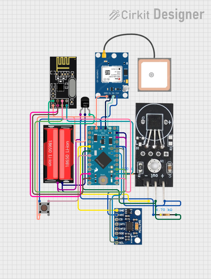
The Arduino Pro Mini is a compact microcontroller board based on the ATmega328P. Designed by Mine, it is ideal for embedded applications and prototyping where space and power efficiency are critical. Its small form factor and low power consumption make it a popular choice for wearable devices, IoT projects, and battery-powered systems.
Explore Projects Built with Arduino Pro Mini
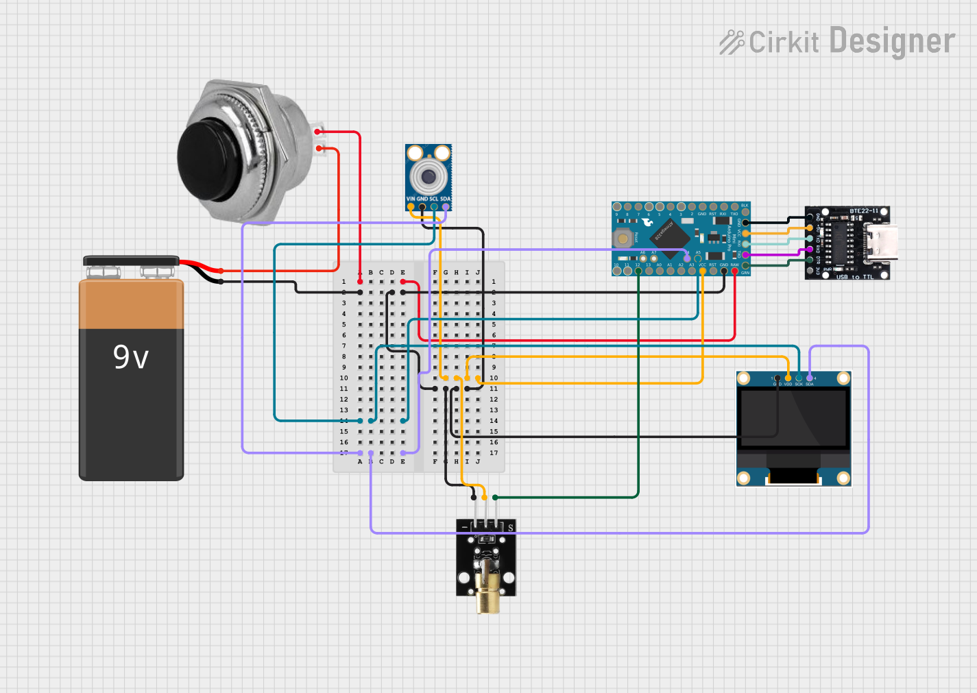
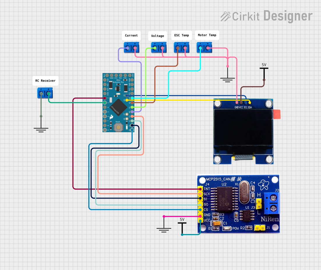
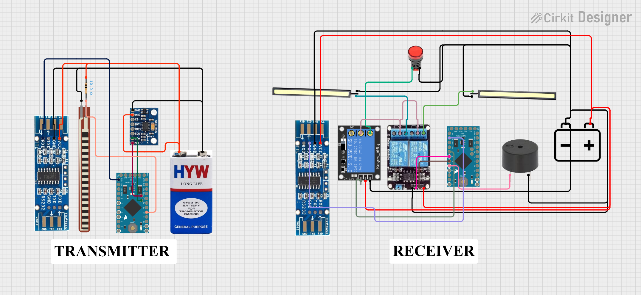
Explore Projects Built with Arduino Pro Mini
Common Applications and Use Cases
- Wearable electronics
- Internet of Things (IoT) devices
- Robotics and automation
- Battery-powered projects
- Prototyping in space-constrained environments
Technical Specifications
The Arduino Pro Mini is available in two voltage and clock speed variants: 3.3V/8MHz and 5V/16MHz. Below are the key technical details:
General Specifications
| Parameter | Value (3.3V Variant) | Value (5V Variant) |
|---|---|---|
| Microcontroller | ATmega328P | ATmega328P |
| Operating Voltage | 3.3V | 5V |
| Clock Speed | 8 MHz | 16 MHz |
| Flash Memory | 32 KB (0.5 KB used by bootloader) | 32 KB (0.5 KB used by bootloader) |
| SRAM | 2 KB | 2 KB |
| EEPROM | 1 KB | 1 KB |
| Digital I/O Pins | 14 (6 PWM outputs) | 14 (6 PWM outputs) |
| Analog Input Pins | 8 | 8 |
| DC Current per I/O Pin | 40 mA | 40 mA |
| Dimensions | 18 mm x 33 mm | 18 mm x 33 mm |
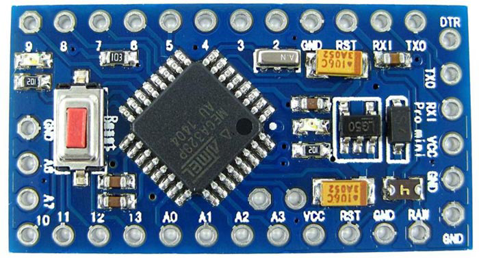
Pin Configuration and Descriptions
The Arduino Pro Mini has a total of 24 pins, including power, digital, and analog pins. Below is the pinout description:
| Pin Name | Description |
|---|---|
| RAW | Unregulated input voltage (up to 12V). Internally regulated to 3.3V or 5V. |
| VCC | Regulated 3.3V or 5V output, depending on the board variant. |
| GND | Ground pin. |
| TX (D1) | Transmit pin for serial communication (UART). |
| RX (D0) | Receive pin for serial communication (UART). |
| D2-D13 | Digital I/O pins. Pins D3, D5, D6, D9, D10, and D11 support PWM. |
| A0-A7 | Analog input pins. Can also be used as digital I/O pins. |
| RST | Reset pin. Pull low to reset the microcontroller. |
Usage Instructions
How to Use the Arduino Pro Mini in a Circuit
Powering the Board:
- Use the RAW pin to supply unregulated voltage (up to 12V). The onboard regulator will convert it to the appropriate operating voltage.
- Alternatively, supply regulated voltage (3.3V or 5V) directly to the VCC pin.
Programming the Board:
- The Arduino Pro Mini does not have a built-in USB interface. Use an external USB-to-Serial adapter (e.g., FTDI adapter) to program the board.
- Connect the FTDI adapter to the Pro Mini as follows:
FTDI Adapter Pin Arduino Pro Mini Pin VCC VCC GND GND TX RX RX TX DTR RST
Uploading Code:
- In the Arduino IDE, select the correct board variant (Arduino Pro or Pro Mini) and processor (ATmega328P (3.3V, 8MHz) or ATmega328P (5V, 16MHz)).
- Choose the appropriate COM port for your FTDI adapter.
- Write or load your sketch and click Upload.
Important Considerations and Best Practices
- Ensure the voltage of your peripherals matches the operating voltage of the Pro Mini (3.3V or 5V).
- Use a decoupling capacitor (e.g., 0.1 µF) between VCC and GND for stable operation.
- Avoid drawing more than 40 mA from any single I/O pin to prevent damage to the microcontroller.
- For battery-powered applications, use the RAW pin to connect the battery for efficient regulation.
Example Code for Arduino Pro Mini with an LED
The following example demonstrates how to blink an LED connected to pin D13:
// Blink an LED connected to pin D13
const int ledPin = 13; // Define the LED pin

void setup() {
  pinMode(ledPin, OUTPUT); // Set pin D13 as an output
}

void loop() {
  digitalWrite(ledPin, HIGH); // Turn the LED on
  delay(1000);                // Wait for 1 second
  digitalWrite(ledPin, LOW);  // Turn the LED off
  delay(1000);                // Wait for 1 second
}
Troubleshooting and FAQs
Common Issues and Solutions
Problem: The board is not detected by the Arduino IDE.
- Solution: Ensure the FTDI adapter is properly connected to the Pro Mini. Check the COM port settings in the Arduino IDE.
Problem: Code upload fails with a "not in sync" error.
- Solution: Verify that the correct board and processor are selected in the Arduino IDE. Ensure the FTDI adapter's DTR pin is connected to the Pro Mini's RST pin.
Problem: The board overheats during operation.
- Solution: Check the input voltage on the RAW pin. Ensure it does not exceed 12V. Verify that the current drawn by peripherals is within safe limits.
Problem: Analog readings are inaccurate.
- Solution: Ensure the reference voltage is stable. Use a decoupling capacitor if necessary.
FAQs
Q1: Can I use the Arduino Pro Mini without an FTDI adapter?
A1: Yes, you can use other USB-to-Serial converters or program the board using an ISP programmer.
Q2: What is the difference between the 3.3V and 5V variants?
A2: The 3.3V variant operates at a lower voltage and clock speed (8 MHz), making it more power-efficient. The 5V variant operates at 16 MHz and is compatible with 5V peripherals.
Q3: Can I power the Pro Mini directly with a LiPo battery?
A3: Yes, you can connect a single-cell LiPo battery (3.7V) to the RAW pin. The onboard regulator will handle the voltage.
Q4: Is the Arduino Pro Mini compatible with Arduino shields?
A4: No, the Pro Mini does not have the standard Arduino shield form factor. However, you can use jumper wires to connect shields or peripherals.