How to Use SparkFun Serial Controlled Motor Driver v20a: Examples, Pinouts, and Specs
Introduction
The SparkFun Serial Controlled Motor Driver v20a (SCMD) is a robust and versatile board designed to control DC and stepper motors through a serial interface. It is an ideal choice for hobbyists and engineers working on robotics, automation projects, or any application requiring precise motor control. The SCMD simplifies the process of integrating motor control into your projects by offering a straightforward serial protocol.
Explore Projects Built with SparkFun Serial Controlled Motor Driver v20a
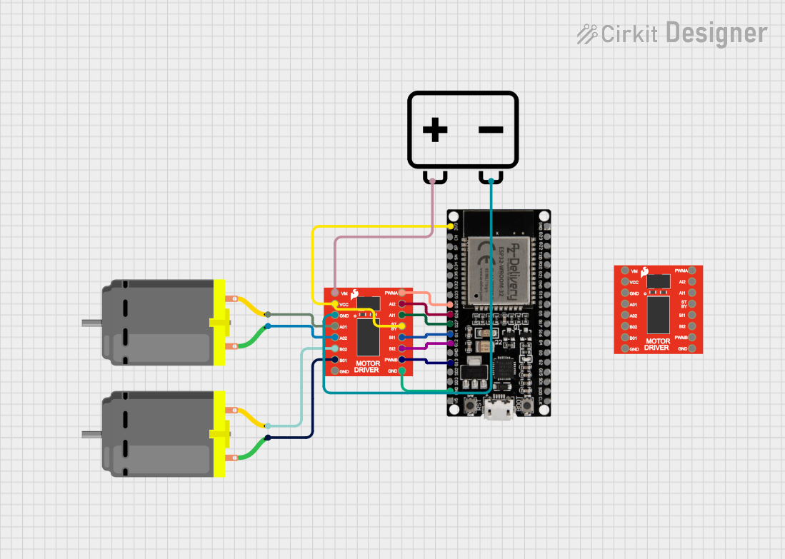
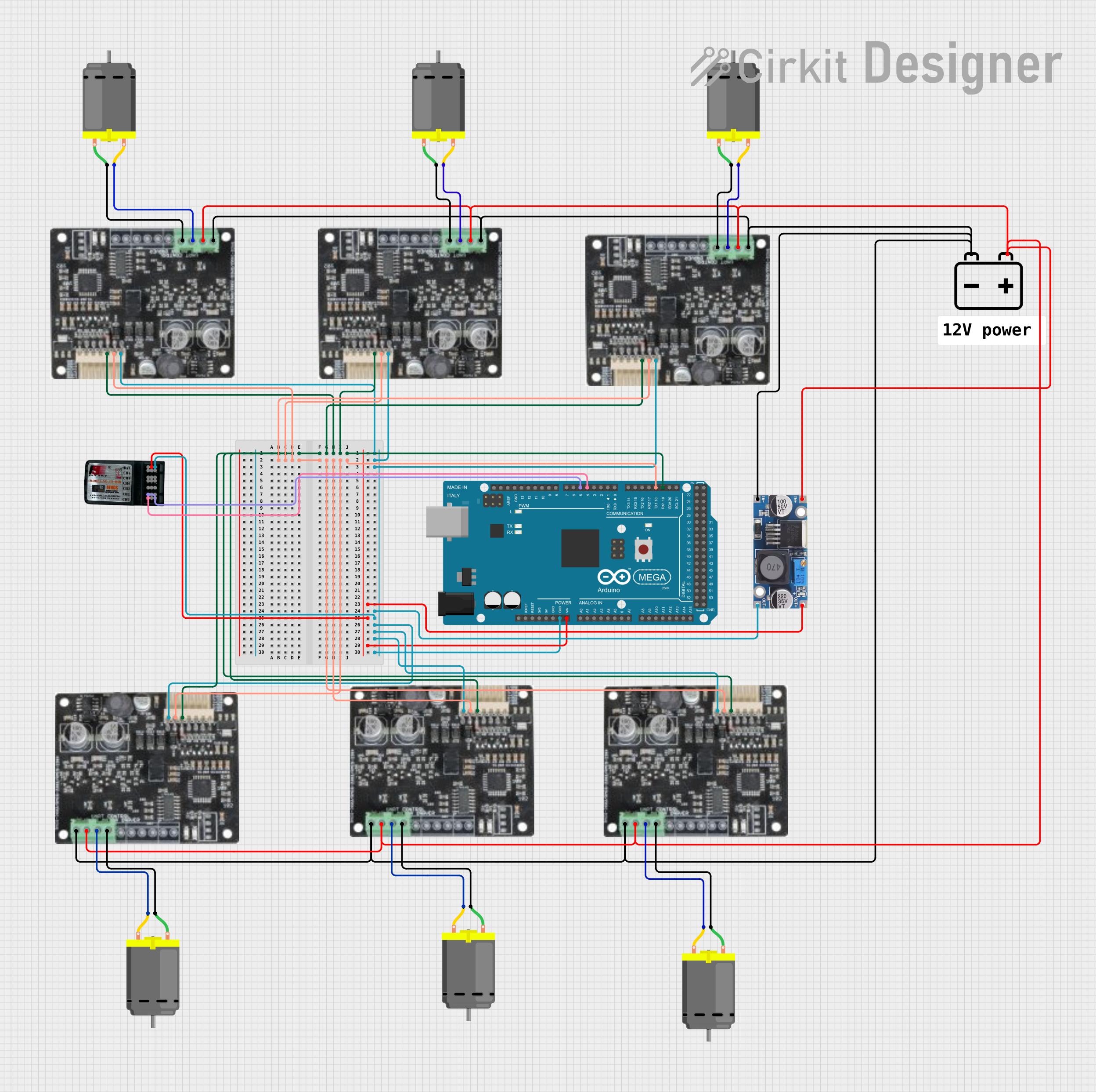
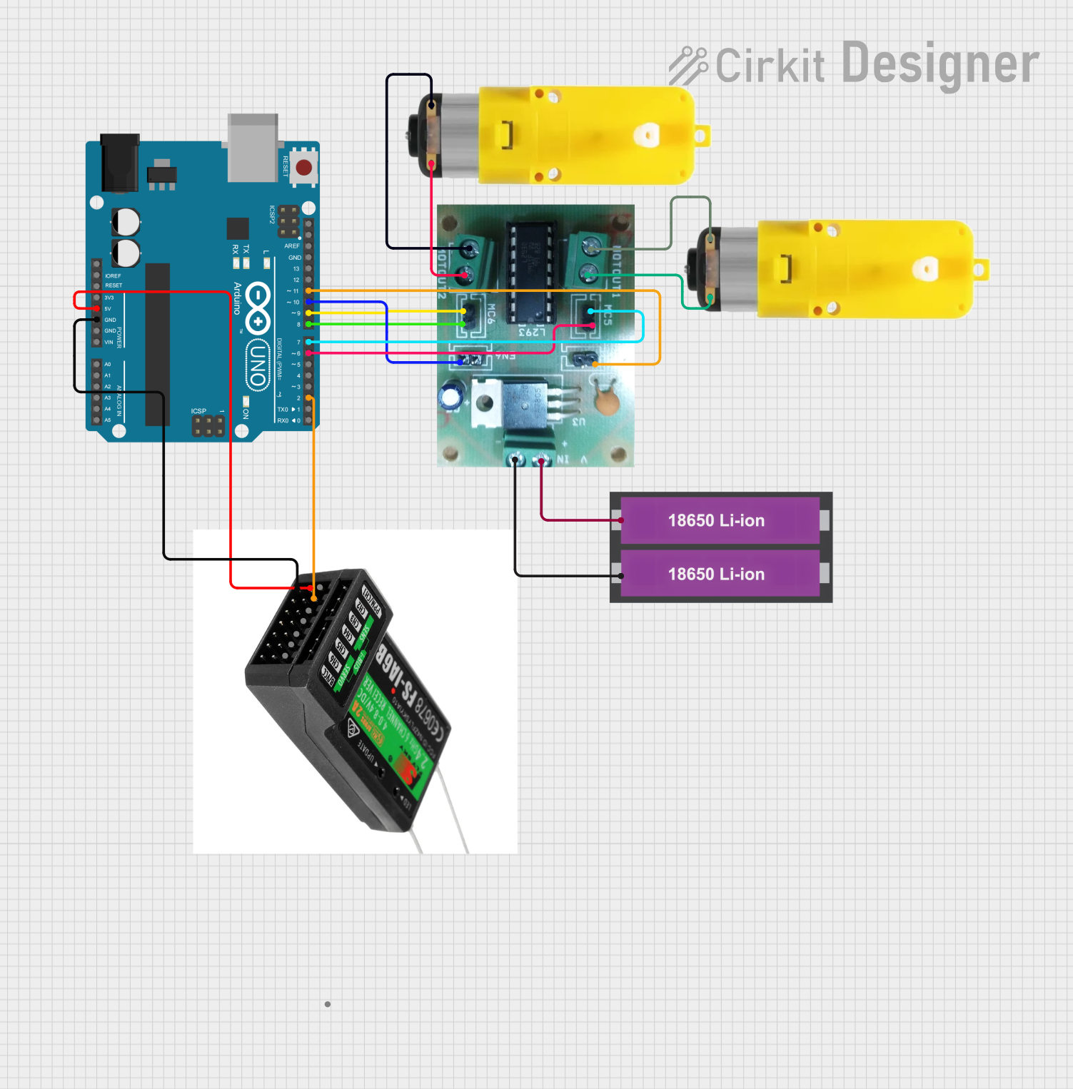
Explore Projects Built with SparkFun Serial Controlled Motor Driver v20a
Common Applications and Use Cases
- Robotics: driving wheels, arms, or other moving parts
- Automation systems: controlling conveyor belts, actuators, or linear guides
- Educational projects: teaching motor control principles and serial communication
- Hobbyist projects: RC vehicles, custom drones, or DIY electronic gadgets
Technical Specifications
Key Technical Details
- Operating Voltage: 6V to 11V
- Continuous Current: Up to 1.2A per channel
- Peak Current: Up to 3.2A per channel for short bursts
- Motor Channels: 2 bidirectional control channels
- Communication: TTL Serial at 9600 bps (default)
- Logic Voltage: 3.3V (5V tolerant)
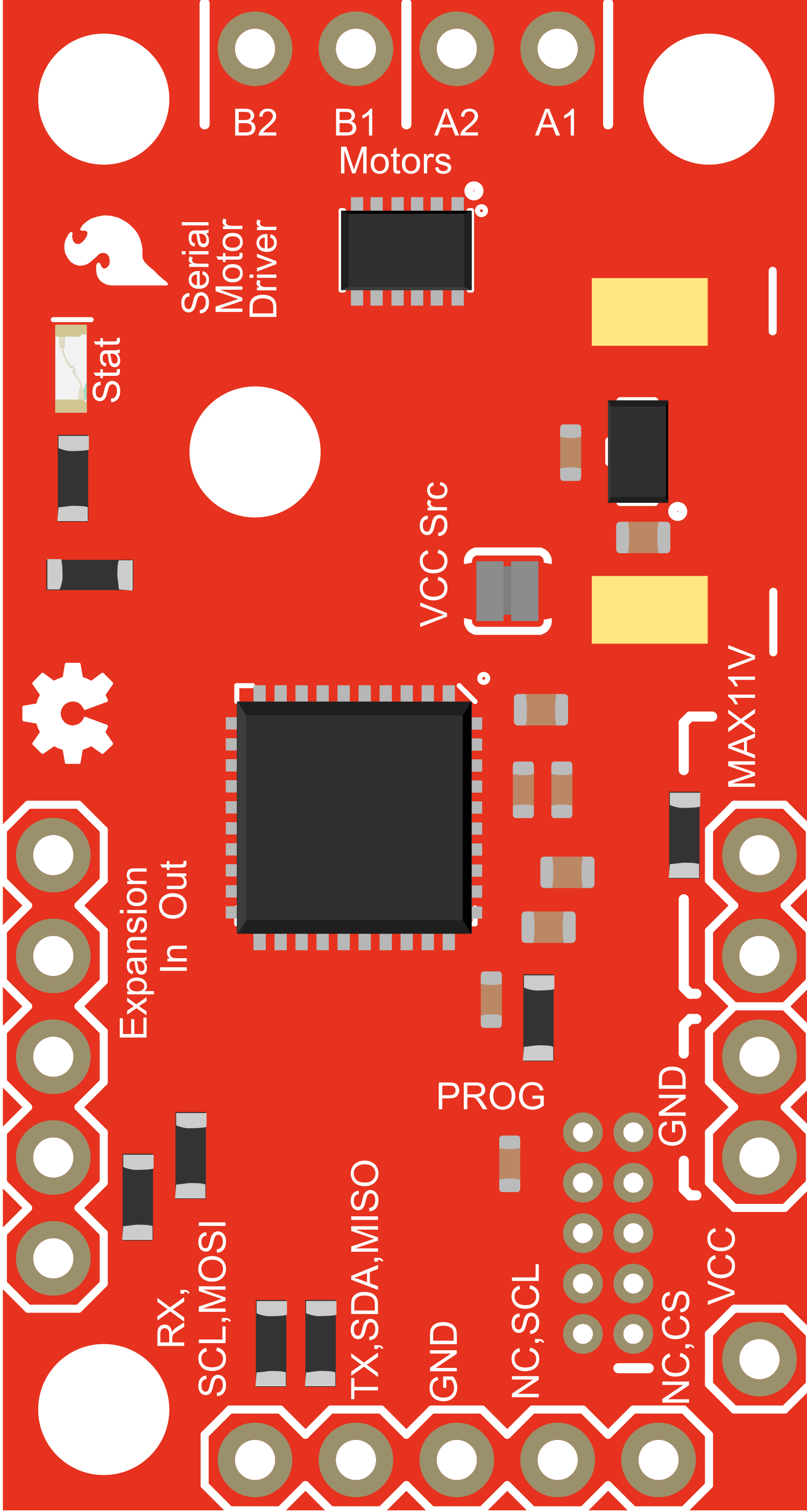
Pin Configuration and Descriptions
| Pin Number | Name | Description |
|---|---|---|
| 1 | GND | Ground connection |
| 2 | VIN | Voltage input for motor power (6V-11V) |
| 3 | 5V | Regulated 5V output (100mA max) |
| 4 | TXO | Serial transmit output to microcontroller |
| 5 | RXI | Serial receive input from microcontroller |
| 6 | A1 | Motor A output 1 |
| 7 | A2 | Motor A output 2 |
| 8 | B1 | Motor B output 1 |
| 9 | B2 | Motor B output 2 |
Usage Instructions
How to Use the Component in a Circuit
Power Connections:
- Connect the motor power supply to VIN and GND.
- Ensure the power supply is within the specified voltage range (6V-11V).
Motor Connections:
- Connect your DC motor leads to the A1/A2 or B1/B2 pairs for motor channels A and B, respectively.
Serial Communication:
- Connect the TXO pin to the RX (receive) pin on your microcontroller.
- Connect the RXI pin to the TX (transmit) pin on your microcontroller.
Logic Power:
- If your microcontroller operates at 3.3V, you can directly connect the logic lines.
- For 5V microcontrollers, ensure that the logic pins are 5V tolerant.
Important Considerations and Best Practices
- Always disconnect the power before making or changing connections to prevent damage.
- Do not exceed the recommended voltage and current specifications.
- Use a separate power supply for the motors and the microcontroller to avoid noise and power spikes.
- Include a flyback diode across the motor terminals if driving inductive loads to protect against voltage spikes.
Example Code for Arduino UNO
#include <SoftwareSerial.h>

SoftwareSerial scmdSerial(10, 11); // RX, TX

void setup() {
  scmdSerial.begin(9600); // Start serial communication at 9600 bps
}

void loop() {
  // Example command to set motor A to full speed forward
  scmdSerial.write(0x88); // Command byte for motor A
  scmdSerial.write(0xFF); // Speed byte (0xFF for full speed)

  delay(2000); // Run for 2 seconds

  // Example command to stop motor A
  scmdSerial.write(0x88); // Command byte for motor A
  scmdSerial.write(0x00); // Speed byte (0x00 to stop)

  delay(2000); // Stop for 2 seconds
}
Note: The example code assumes that you have connected the SCMD TXO pin to pin 10 on the Arduino and the RXI pin to pin 11. Adjust the pin numbers in the SoftwareSerial constructor as needed for your setup.
Troubleshooting and FAQs
Common Issues
- Motor not responding: Check all connections, ensure power supply is within the specified range, and verify that the serial commands are being sent correctly.
- Unexpected motor behavior: Double-check the command bytes and speed values being sent. Ensure there is no electrical noise affecting the signals.
Solutions and Tips for Troubleshooting
- Use a multimeter to verify the voltage at VIN and the continuity of the motor connections.
- Implement a simple serial echo test to ensure that the microcontroller and SCMD are communicating properly.
- If using long wires or in a noisy environment, consider using shielded cables or twisted pairs for the serial lines.
FAQs
Q: Can I control stepper motors with the SCMD? A: Yes, the SCMD can control stepper motors. You will need to send the appropriate serial commands to control the stepping sequence.
Q: What is the default baud rate for serial communication? A: The default baud rate is 9600 bps. If you need to change it, refer to the SCMD documentation for the correct command sequence.
Q: How do I change the direction of the motor? A: To change the direction, you need to send a different command byte or speed value that corresponds to the reverse direction.
Q: Can I use the SCMD with a 5V microcontroller? A: Yes, the logic pins on the SCMD are 5V tolerant, but ensure that your microcontroller's TX and RX pins are also 3.3V tolerant.
For further assistance, consult the SparkFun Serial Controlled Motor Driver v20a user manual or contact SparkFun's technical support.