Cirkit Designer Logo
Cirkit Designer
Your all-in-one circuit design IDE
Home / 
Component Documentation

How to Use 5V to 12V Step-up Converter: Examples, Pinouts, and Specs

Image of 5V to 12V Step-up Converter
Cirkit Designer LogoDesign with 5V to 12V Step-up Converter in Cirkit Designer

Introduction

A 5V to 12V Step-up Converter is an electronic device that efficiently increases a low input voltage level of 5 volts to a higher output voltage level of 12 volts. This type of DC-DC converter is essential in applications where the available power supply voltage is lower than what is required by the electronic circuit or device. Common applications include battery-powered devices, portable electronics, and systems that require a stable 12V supply from a USB or other 5V sources.

Explore Projects Built with 5V to 12V Step-up Converter

Use Cirkit Designer to design, explore, and prototype these projects online. Some projects support real-time simulation. Click "Open Project" to start designing instantly!
Arduino Mega 2560-Based Robotic System with Stepper Motors and IR Sensors
Image of FYP: A project utilizing 5V to 12V Step-up Converter in a practical application
This circuit is a control system powered by a 12V to 5V step-down converter, featuring an Arduino Mega 2560 microcontroller that interfaces with various sensors (IR sensors, limit switch), actuators (servos, stepper motors), and a 20x4 LCD display. The system is designed to monitor inputs from sensors and control outputs to motors and display information, suitable for applications like automation or robotics.
Cirkit Designer LogoOpen Project in Cirkit Designer
Battery-Powered DC Generator with XL4015 Buck Converter
Image of conveyor: A project utilizing 5V to 12V Step-up Converter in a practical application
This circuit consists of a 12V battery connected to a rocker switch, which controls the input to an XL4015 DC Buck Step-down converter. The converter steps down the voltage to power a DC generator, with the generator's output connected back to the converter to form a feedback loop.
Cirkit Designer LogoOpen Project in Cirkit Designer
12V to 5V Power Supply with LED Indicator and Push Switch
Image of Power Supply LVCO: A project utilizing 5V to 12V Step-up Converter in a practical application
This circuit is a 12V to 5V regulated power supply with an LED indicator. It uses a 5408 diode for reverse polarity protection, an LM340T5 7805 voltage regulator to step down the voltage to 5V, and a push switch to control the LED indicator. The circuit also includes capacitors for filtering and a resistor to limit the current through the LED.
Cirkit Designer LogoOpen Project in Cirkit Designer
Solar-Powered Battery Charging System with 12V to 5V Step-Down Converter
Image of power circuit: A project utilizing 5V to 12V Step-up Converter in a practical application
This circuit is designed to harness solar energy to charge a 12V battery using a solar charge controller. The stored energy in the battery is then stepped down to 5V using a step-down power converter, providing a stable 5V output for other devices.
Cirkit Designer LogoOpen Project in Cirkit Designer

Explore Projects Built with 5V to 12V Step-up Converter

Use Cirkit Designer to design, explore, and prototype these projects online. Some projects support real-time simulation. Click "Open Project" to start designing instantly!
Image of FYP: A project utilizing 5V to 12V Step-up Converter in a practical application
Arduino Mega 2560-Based Robotic System with Stepper Motors and IR Sensors
This circuit is a control system powered by a 12V to 5V step-down converter, featuring an Arduino Mega 2560 microcontroller that interfaces with various sensors (IR sensors, limit switch), actuators (servos, stepper motors), and a 20x4 LCD display. The system is designed to monitor inputs from sensors and control outputs to motors and display information, suitable for applications like automation or robotics.
Cirkit Designer LogoOpen Project in Cirkit Designer
Image of conveyor: A project utilizing 5V to 12V Step-up Converter in a practical application
Battery-Powered DC Generator with XL4015 Buck Converter
This circuit consists of a 12V battery connected to a rocker switch, which controls the input to an XL4015 DC Buck Step-down converter. The converter steps down the voltage to power a DC generator, with the generator's output connected back to the converter to form a feedback loop.
Cirkit Designer LogoOpen Project in Cirkit Designer
Image of Power Supply LVCO: A project utilizing 5V to 12V Step-up Converter in a practical application
12V to 5V Power Supply with LED Indicator and Push Switch
This circuit is a 12V to 5V regulated power supply with an LED indicator. It uses a 5408 diode for reverse polarity protection, an LM340T5 7805 voltage regulator to step down the voltage to 5V, and a push switch to control the LED indicator. The circuit also includes capacitors for filtering and a resistor to limit the current through the LED.
Cirkit Designer LogoOpen Project in Cirkit Designer
Image of power circuit: A project utilizing 5V to 12V Step-up Converter in a practical application
Solar-Powered Battery Charging System with 12V to 5V Step-Down Converter
This circuit is designed to harness solar energy to charge a 12V battery using a solar charge controller. The stored energy in the battery is then stepped down to 5V using a step-down power converter, providing a stable 5V output for other devices.
Cirkit Designer LogoOpen Project in Cirkit Designer

Technical Specifications

Key Technical Details

  • Input Voltage (Vin): 5V DC
  • Output Voltage (Vout): 12V DC
  • Maximum Output Current: Specified by the model (e.g., 1A)
  • Efficiency: Typically >90% under full load
  • Switching Frequency: Specified by the model (e.g., 1.5MHz)
  • Operating Temperature Range: -40°C to +85°C

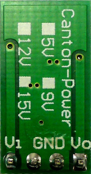
Pin Configuration and Descriptions

Pin Number Name Description
1 GND Ground reference for the input voltage
2 Vin Input voltage (5V)
3 Vout Output voltage (12V)
4 GND Ground reference for the output voltage

Usage Instructions

How to Use the Component in a Circuit

  1. Connecting Input Power: Connect the 5V power supply to the Vin and GND pins. Ensure that the power supply can provide sufficient current for the expected load.

  2. Connecting the Load: Attach the device or circuit requiring 12V to the Vout and GND pins. Ensure that the load does not exceed the maximum output current rating of the converter.

  3. Powering On: Once the connections are secure, power on the 5V supply. The step-up converter will begin converting the voltage to 12V.

Important Considerations and Best Practices

  • Capacitive Loading: Some converters may require a minimum load capacitance on the output for stable operation. Refer to the datasheet for specifics.
  • Thermal Management: Ensure adequate ventilation or heat sinking if the converter is expected to operate near its maximum power rating.
  • Input Voltage: Do not exceed the recommended input voltage as it may damage the converter.
  • Output Voltage Ripple: For sensitive applications, additional filtering may be required to reduce voltage ripple.

Troubleshooting and FAQs

Common Issues

  • Insufficient Output Voltage: Check if the input voltage is stable and within the specified range. Also, verify that the load does not exceed the maximum current rating.
  • Overheating: Ensure that the converter is not operating above its rated current and that there is sufficient heat dissipation.
  • Noise Issues: Switching converters can generate electromagnetic interference (EMI). Proper layout, grounding, and filtering can mitigate this.

Solutions and Tips for Troubleshooting

  • Output Voltage Measurement: Use a multimeter to measure the output voltage under load and ensure it is close to 12V.
  • Input Power Quality: Ensure the input power source is stable and clean. A low-quality power source can affect the converter's performance.
  • Check Connections: Loose or poor connections can cause voltage drops and erratic behavior.

FAQs

Q: Can I adjust the output voltage of the step-up converter? A: Some models may offer an adjustable output via a feedback pin or potentiometer. Check the specific model's datasheet.

Q: Is it possible to parallel two converters for more current? A: Paralleling converters is generally not recommended unless they are specifically designed for that purpose.

Q: How do I choose the right converter for my application? A: Consider the maximum output current, efficiency, physical size, and thermal requirements for your application.

Example Code for Arduino UNO

If you're using the step-up converter with an Arduino UNO to power a 12V component, here's an example of how you might control it via a digital pin:

// Define the control pin
const int controlPin = 7;

void setup() {
  // Set the control pin as an output
  pinMode(controlPin, OUTPUT);
}

void loop() {
  // Turn on the step-up converter
  digitalWrite(controlPin, HIGH);
  delay(5000); // Keep the converter on for 5 seconds

  // Turn off the step-up converter
  digitalWrite(controlPin, LOW);
  delay(5000); // Keep the converter off for 5 seconds
}

Note: This code assumes that the step-up converter can be controlled by a digital signal, which may not be the case for all converters. Always refer to the specific converter's datasheet for accurate control methods.