How to Use OSOYOO Nano Breakout Board: Examples, Pinouts, and Specs
Introduction
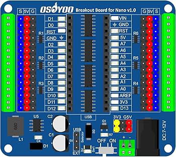
The OSOYOO Nano Breakout Board is a compact and versatile development board designed specifically for the Arduino Nano. It provides easy access to all the Nano's pins and includes additional components to simplify prototyping and experimentation. This breakout board is ideal for hobbyists, students, and professionals who want to streamline their development process with the Arduino Nano.
Explore Projects Built with OSOYOO Nano Breakout Board
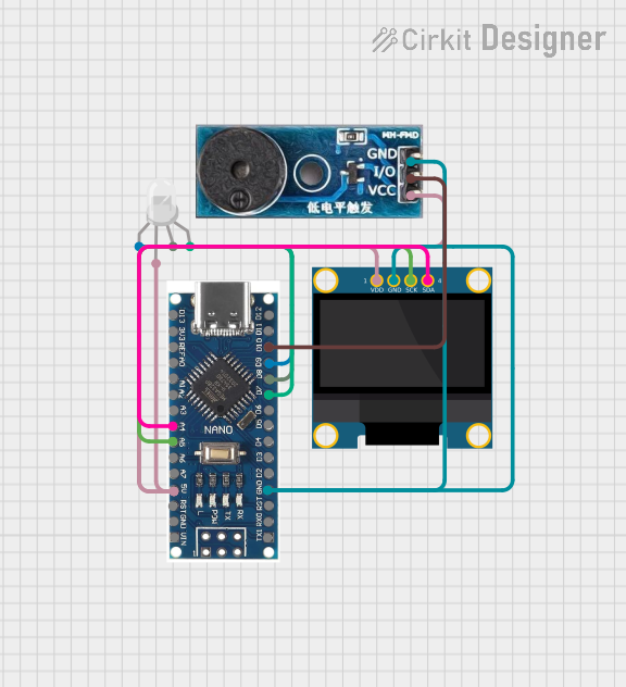
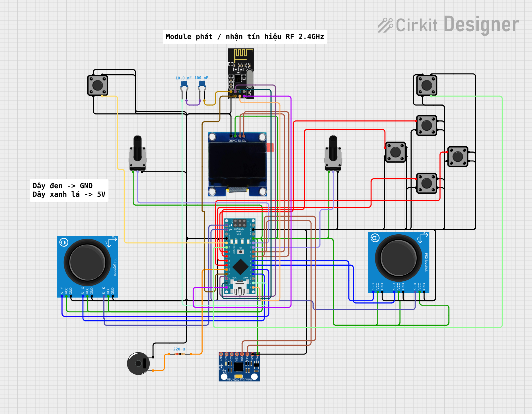

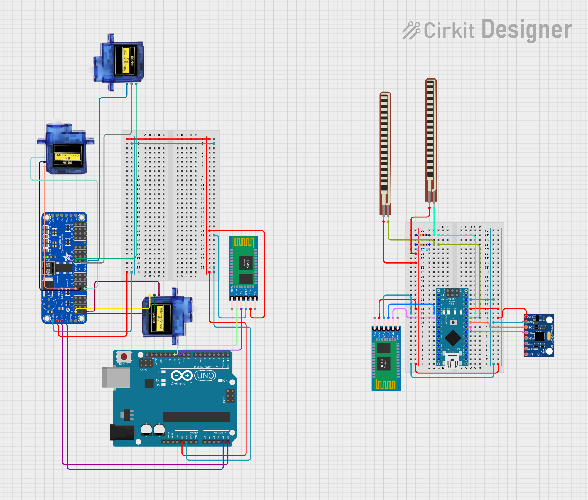
Explore Projects Built with OSOYOO Nano Breakout Board
Common Applications and Use Cases
- Rapid prototyping of Arduino Nano-based projects
- Educational purposes for learning microcontroller programming
- Building IoT devices and small-scale automation systems
- Experimenting with sensors, actuators, and other peripherals
- Creating compact and organized circuit layouts
Technical Specifications
The OSOYOO Nano Breakout Board is designed to enhance the functionality of the Arduino Nano by providing a user-friendly interface and additional features. Below are the key technical details:
General Specifications
- Compatible Microcontroller: Arduino Nano (ATmega328P or ATmega168)
- Input Voltage: 6V–12V (via VIN pin) or 5V (via USB)
- Output Voltage: 5V and 3.3V regulated outputs
- Dimensions: 60mm x 55mm
- Weight: ~20g
- Operating Temperature: -40°C to 85°C
Pin Configuration and Descriptions
The breakout board provides labeled pin headers for easy access to the Arduino Nano's pins. Below is the pin configuration:
| Pin | Description |
|---|---|
| VIN | Input voltage (6V–12V) for powering the board and Arduino Nano. |
| GND | Ground connection. |
| 5V | Regulated 5V output for powering external components. |
| 3.3V | Regulated 3.3V output for low-voltage peripherals. |
| Digital Pins | D0–D13: Digital I/O pins for general-purpose input/output. |
| Analog Pins | A0–A7: Analog input pins for reading sensor data. |
| TX/RX | Serial communication pins for UART (TX: transmit, RX: receive). |
| Reset | Resets the Arduino Nano. |
| I2C | SDA (A4) and SCL (A5): I2C communication pins for connecting I2C devices. |
| SPI | MOSI, MISO, SCK: SPI communication pins for high-speed data transfer. |
| Power Header | Additional headers for connecting external power sources or peripherals. |
Additional Features
- Onboard power LED indicator
- Reset button for Arduino Nano
- Screw terminals for secure power connections
- Breadboard-compatible design for easy prototyping
Usage Instructions
How to Use the OSOYOO Nano Breakout Board
- Insert the Arduino Nano: Align the Nano's pins with the breakout board's headers and gently press it into place.
- Power the Board:
- Use the VIN pin for external power (6V–12V).
- Alternatively, connect the board to a computer via USB for 5V power.
- Connect Peripherals:
- Use the labeled pin headers to connect sensors, actuators, or other components.
- Utilize the 5V or 3.3V pins to power external devices.
- Program the Arduino Nano:
- Connect the Nano to your computer via USB.
- Use the Arduino IDE to write and upload your code.
Important Considerations and Best Practices
- Voltage Levels: Ensure that connected components operate within the 5V or 3.3V range to avoid damage.
- Power Supply: Avoid exceeding the recommended input voltage (12V) to prevent overheating.
- Pin Usage: Double-check pin assignments in your code to avoid conflicts or incorrect connections.
- Static Precautions: Handle the board with care to prevent electrostatic discharge (ESD) damage.
Example Code for Arduino Nano
Below is an example of how to use the OSOYOO Nano Breakout Board with an LED connected to digital pin D13:
// Example: Blink an LED connected to pin D13 on the OSOYOO Nano Breakout Board

// Define the pin number for the LED
const int ledPin = 13;

void setup() {
  // Set the LED pin as an output
  pinMode(ledPin, OUTPUT);
}

void loop() {
  // Turn the LED on
  digitalWrite(ledPin, HIGH);
  delay(1000); // Wait for 1 second

  // Turn the LED off
  digitalWrite(ledPin, LOW);
  delay(1000); // Wait for 1 second
}
Troubleshooting and FAQs
Common Issues and Solutions
Arduino Nano Not Detected by Computer:
- Ensure the USB cable is properly connected.
- Verify that the correct COM port is selected in the Arduino IDE.
- Install the necessary drivers for the Arduino Nano.
No Power to the Board:
- Check the power source and ensure it meets the voltage requirements.
- Inspect the connections to the VIN or USB port.
Components Not Responding:
- Verify that the components are connected to the correct pins.
- Check for loose or faulty connections.
Overheating:
- Ensure the input voltage does not exceed 12V.
- Avoid drawing excessive current from the 5V or 3.3V pins.
FAQs
Q: Can I use the OSOYOO Nano Breakout Board with other microcontrollers?
A: The board is specifically designed for the Arduino Nano. While it may be possible to adapt it for other microcontrollers, compatibility is not guaranteed.
Q: Is the board compatible with both the ATmega328P and ATmega168 versions of the Arduino Nano?
A: Yes, the OSOYOO Nano Breakout Board is compatible with both versions.
Q: Can I use the board for I2C and SPI communication simultaneously?
A: Yes, the board provides separate pins for I2C (A4, A5) and SPI (MOSI, MISO, SCK), allowing simultaneous use.
Q: Does the board include onboard sensors or modules?
A: No, the OSOYOO Nano Breakout Board is a prototyping platform and does not include onboard sensors or modules.
By following this documentation, you can effectively utilize the OSOYOO Nano Breakout Board for your Arduino Nano projects.