Cirkit Designer Logo
Cirkit Designer
Your all-in-one circuit design IDE
Home / 
Component Documentation

How to Use TTL - RS485: Examples, Pinouts, and Specs

Image of TTL - RS485
Cirkit Designer LogoDesign with TTL - RS485 in Cirkit Designer

Introduction

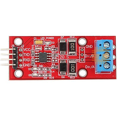
The TTL to RS485 converter is a versatile electronic component that facilitates the conversion of TTL (Transistor-Transistor Logic) signals to RS485 protocol. RS485 is a robust communication standard designed for long-distance and noise-resistant data transmission. This converter is widely used in industrial automation, sensor networks, and other applications requiring reliable communication over extended distances.

Explore Projects Built with TTL - RS485

Use Cirkit Designer to design, explore, and prototype these projects online. Some projects support real-time simulation. Click "Open Project" to start designing instantly!
Arduino UNO and Relay-Controlled RS485 Communication System
Image of Diagrama: A project utilizing TTL - RS485 in a practical application
This circuit features an Arduino UNO microcontroller interfaced with a 4-channel relay module and a UART TTL to RS485 converter. The Arduino controls the relays via digital pins and communicates with the RS485 converter for serial communication, enabling control of external devices and communication over long distances.
Cirkit Designer LogoOpen Project in Cirkit Designer
STM32 and Arduino UNO Based Dual RS485 Communication Interface
Image of STM to Arduino RS485: A project utilizing TTL - RS485 in a practical application
This circuit consists of two microcontrollers, an STM32F103C8T6 and an Arduino UNO, each interfaced with separate RS485 transceiver modules for serial communication. The STM32F103C8T6 controls the RE (Receiver Enable) and DE (Driver Enable) pins of one RS485 module to manage its operation, and communicates via the A9 and A10 pins for DI (Data Input) and RO (Receiver Output), respectively. The Arduino UNO is similarly connected to another RS485 module, with digital pins D2 and D3 interfacing with DI and RO, and D8 controlling both RE and DE. The RS485 modules are connected to each other through their A and B differential communication lines, enabling serial data exchange between the two microcontrollers over a robust and long-distance capable RS485 network.
Cirkit Designer LogoOpen Project in Cirkit Designer
RS485-Enabled NPK Soil Sensor Interface
Image of NPK: A project utilizing TTL - RS485 in a practical application
This circuit connects an NPK Soil Sensor to an RS485 transceiver module. The sensor's VCC and GND pins are connected to the corresponding VCC and GND pins on the RS485 module to provide power. The sensor's analog output (A) and digital output (B) are interfaced with the RS485 module's DI (Data Input) and DE (Driver Enable) pins, respectively, allowing the sensor's signals to be transmitted over an RS485 communication bus.
Cirkit Designer LogoOpen Project in Cirkit Designer
Arduino UNO R4 WiFi and RS485 to TTL Interface Circuit with Pushbutton and LED Indicators
Image of ModbusRTU : RS485 to TTL (UART): A project utilizing TTL - RS485 in a practical application
This circuit features two Arduino UNO R4 WiFi boards interfaced with RS485 to TTL converters, enabling serial communication over RS485 protocol. A pushbutton is connected to one of the Arduino boards, potentially to initiate communication or control actions. Additionally, there are two LEDs with series resistors, each connected to a separate Arduino, likely indicating the status or providing visual feedback for operations.
Cirkit Designer LogoOpen Project in Cirkit Designer

Explore Projects Built with TTL - RS485

Use Cirkit Designer to design, explore, and prototype these projects online. Some projects support real-time simulation. Click "Open Project" to start designing instantly!
Image of Diagrama: A project utilizing TTL - RS485 in a practical application
Arduino UNO and Relay-Controlled RS485 Communication System
This circuit features an Arduino UNO microcontroller interfaced with a 4-channel relay module and a UART TTL to RS485 converter. The Arduino controls the relays via digital pins and communicates with the RS485 converter for serial communication, enabling control of external devices and communication over long distances.
Cirkit Designer LogoOpen Project in Cirkit Designer
Image of STM to Arduino RS485: A project utilizing TTL - RS485 in a practical application
STM32 and Arduino UNO Based Dual RS485 Communication Interface
This circuit consists of two microcontrollers, an STM32F103C8T6 and an Arduino UNO, each interfaced with separate RS485 transceiver modules for serial communication. The STM32F103C8T6 controls the RE (Receiver Enable) and DE (Driver Enable) pins of one RS485 module to manage its operation, and communicates via the A9 and A10 pins for DI (Data Input) and RO (Receiver Output), respectively. The Arduino UNO is similarly connected to another RS485 module, with digital pins D2 and D3 interfacing with DI and RO, and D8 controlling both RE and DE. The RS485 modules are connected to each other through their A and B differential communication lines, enabling serial data exchange between the two microcontrollers over a robust and long-distance capable RS485 network.
Cirkit Designer LogoOpen Project in Cirkit Designer
Image of NPK: A project utilizing TTL - RS485 in a practical application
RS485-Enabled NPK Soil Sensor Interface
This circuit connects an NPK Soil Sensor to an RS485 transceiver module. The sensor's VCC and GND pins are connected to the corresponding VCC and GND pins on the RS485 module to provide power. The sensor's analog output (A) and digital output (B) are interfaced with the RS485 module's DI (Data Input) and DE (Driver Enable) pins, respectively, allowing the sensor's signals to be transmitted over an RS485 communication bus.
Cirkit Designer LogoOpen Project in Cirkit Designer
Image of ModbusRTU : RS485 to TTL (UART): A project utilizing TTL - RS485 in a practical application
Arduino UNO R4 WiFi and RS485 to TTL Interface Circuit with Pushbutton and LED Indicators
This circuit features two Arduino UNO R4 WiFi boards interfaced with RS485 to TTL converters, enabling serial communication over RS485 protocol. A pushbutton is connected to one of the Arduino boards, potentially to initiate communication or control actions. Additionally, there are two LEDs with series resistors, each connected to a separate Arduino, likely indicating the status or providing visual feedback for operations.
Cirkit Designer LogoOpen Project in Cirkit Designer

Common Applications and Use Cases

  • Industrial automation systems
  • Communication between microcontrollers and RS485 devices
  • Long-distance data transmission in noisy environments
  • Sensor networks and IoT applications
  • Serial communication in robotics and embedded systems

Technical Specifications

The TTL to RS485 converter is designed to operate efficiently in a variety of environments. Below are its key technical details:

General Specifications

Parameter Value
Operating Voltage 3.3V to 5V
Communication Protocol RS485
Baud Rate Up to 115200 bps
Transmission Distance Up to 1200 meters (4000 feet)
Operating Temperature -40°C to 85°C
Power Consumption Low power

Pin Configuration and Descriptions

Pin Name Direction Description
VCC Input Power supply input (3.3V to 5V)
GND Input Ground connection
DI Input Data input (TTL signal from microcontroller)
RO Output Data output (TTL signal to microcontroller)
DE Input Driver enable (active high to enable transmission)
RE Input Receiver enable (active low to enable reception)
A Output RS485 differential signal (non-inverting)
B Output RS485 differential signal (inverting)

Usage Instructions

How to Use the Component in a Circuit

  1. Power the Converter: Connect the VCC pin to a 3.3V or 5V power source and the GND pin to ground.
  2. Connect TTL Signals:
    • Connect the DI pin to the TTL data output of your microcontroller.
    • Connect the RO pin to the TTL data input of your microcontroller.
  3. Enable Transmission and Reception:
    • Set the DE pin high to enable data transmission.
    • Set the RE pin low to enable data reception.
  4. Connect RS485 Bus:
    • Connect the A and B pins to the RS485 bus for differential signaling.
  5. Termination Resistor: If the converter is at the end of the RS485 bus, connect a 120-ohm termination resistor between the A and B pins to prevent signal reflections.

Important Considerations and Best Practices

  • Ensure proper grounding between all devices on the RS485 bus to avoid communication errors.
  • Use twisted-pair cables for the RS485 bus to minimize noise and signal degradation.
  • Avoid exceeding the maximum transmission distance (1200 meters) or baud rate (115200 bps) for reliable communication.
  • If using multiple devices on the RS485 bus, ensure that only one device is transmitting at a time to prevent data collisions.

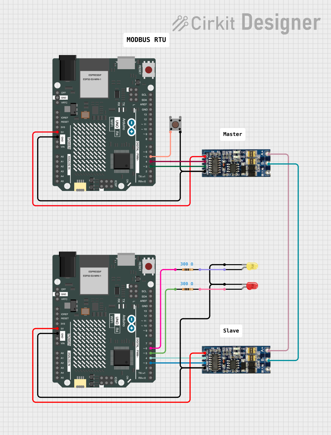
Example: Connecting to an Arduino UNO

Below is an example of how to use the TTL to RS485 converter with an Arduino UNO for serial communication:

// Example: Arduino UNO with TTL to RS485 Converter
// This code demonstrates sending and receiving data over RS485

#define DE_PIN 2  // Driver Enable pin connected to Arduino pin 2
#define RE_PIN 3  // Receiver Enable pin connected to Arduino pin 3

void setup() {
  Serial.begin(9600); // Initialize serial communication at 9600 bps
  pinMode(DE_PIN, OUTPUT); // Set DE pin as output
  pinMode(RE_PIN, OUTPUT); // Set RE pin as output

  // Enable receiver and disable transmitter initially
  digitalWrite(DE_PIN, LOW);
  digitalWrite(RE_PIN, LOW);
}

void loop() {
  // Example: Sending data
  digitalWrite(DE_PIN, HIGH); // Enable transmitter
  digitalWrite(RE_PIN, HIGH); // Disable receiver
  Serial.println("Hello, RS485!"); // Send data
  delay(1000); // Wait for 1 second

  // Example: Receiving data
  digitalWrite(DE_PIN, LOW); // Disable transmitter
  digitalWrite(RE_PIN, LOW); // Enable receiver
  if (Serial.available()) {
    String receivedData = Serial.readString(); // Read incoming data
    Serial.println("Received: " + receivedData); // Print received data
  }
}

Troubleshooting and FAQs

Common Issues and Solutions

  1. No Communication Between Devices:

    • Verify that the A and B pins are correctly connected to the RS485 bus.
    • Check the DE and RE pin states to ensure proper transmission and reception.
    • Ensure all devices on the RS485 bus share a common ground.
  2. Data Corruption or Noise:

    • Use shielded or twisted-pair cables for the RS485 bus.
    • Add a 120-ohm termination resistor at both ends of the RS485 bus.
  3. Short Transmission Distance:

    • Check the power supply voltage and ensure it meets the converter's requirements.
    • Reduce the baud rate to improve signal integrity over longer distances.
  4. Multiple Devices Not Communicating:

    • Ensure only one device is transmitting at a time.
    • Use unique addresses or identifiers for each device in the communication protocol.

FAQs

Q: Can I use the TTL to RS485 converter with a 3.3V microcontroller?
A: Yes, the converter supports both 3.3V and 5V logic levels.

Q: How many devices can I connect to the RS485 bus?
A: RS485 supports up to 32 devices on a single bus without additional hardware.

Q: Do I need to use a termination resistor?
A: Yes, termination resistors are recommended at both ends of the RS485 bus to prevent signal reflections.

Q: What is the maximum baud rate supported?
A: The converter supports baud rates up to 115200 bps.