How to Use poortdeler: Examples, Pinouts, and Specs
Introduction
A poortdeler, or voltage divider, is a fundamental electronic circuit used to reduce an input voltage to a lower output voltage. It operates based on the principle of resistive voltage division, where the output voltage is determined by the ratio of two resistors in series. This component is widely used in applications where a specific voltage level is required, such as in signal conditioning, sensor interfacing, and analog-to-digital conversion.
Explore Projects Built with poortdeler


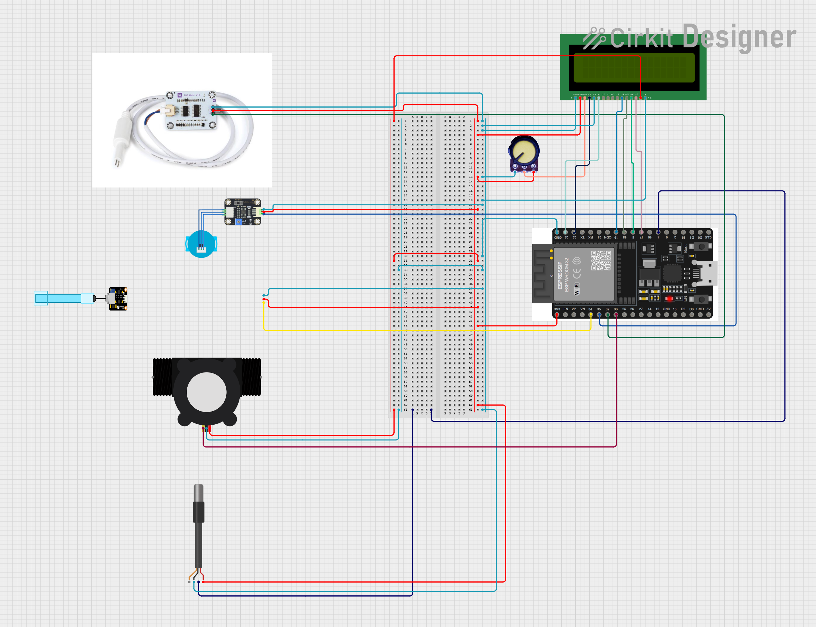
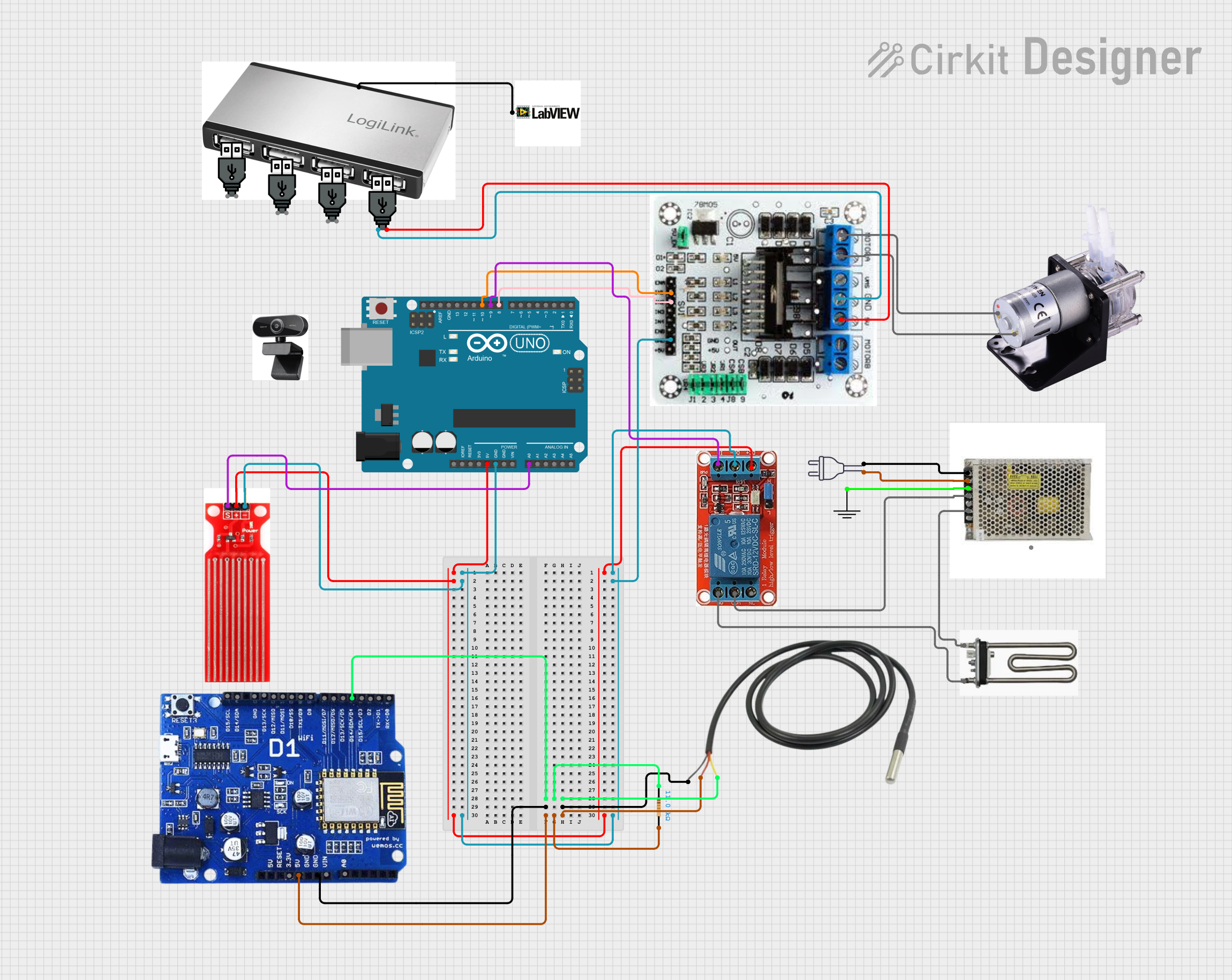
Explore Projects Built with poortdeler
Common Applications and Use Cases
- Signal Conditioning: Adjusting signal levels for compatibility with other components.
- Sensor Interfacing: Scaling sensor output voltages to match microcontroller input ranges.
- Voltage Measurement: Measuring high voltages using low-voltage ADCs.
- Biasing Circuits: Providing reference voltages for transistors or operational amplifiers.
Technical Specifications
The poortdeler is not a single physical component but a circuit made up of two resistors. The key parameters depend on the resistor values and the input voltage. Below are the general specifications:
Key Technical Details
- Input Voltage (Vin): Up to the maximum voltage rating of the resistors.
- Output Voltage (Vout): Determined by the formula: [ V_{out} = V_{in} \times \frac{R_2}{R_1 + R_2} ]
- Resistor Power Rating: Typically 0.25W or higher, depending on the current through the resistors.
- Accuracy: Dependent on the tolerance of the resistors used (e.g., ±1%, ±5%).
Pin Configuration and Descriptions
The poortdeler circuit has three key points of connection:
| Pin Name | Description |
|---|---|
| Vin | Input voltage to the voltage divider. |
| Vout | Output voltage, which is a fraction of the input voltage. |
| GND | Ground connection, common to both resistors and the input voltage source. |
Usage Instructions
How to Use the Poortdeler in a Circuit
Select Resistor Values: Choose two resistors, ( R_1 ) and ( R_2 ), based on the desired output voltage: [ V_{out} = V_{in} \times \frac{R_2}{R_1 + R_2} ] For example, to divide a 10V input to 5V output, use ( R_1 = R_2 ).
Connect the Resistors:
- Connect ( R_1 ) between the input voltage (Vin) and the output node.
- Connect ( R_2 ) between the output node and ground (GND).
Verify the Output Voltage: Measure the output voltage using a multimeter to ensure it matches the desired value.
Important Considerations and Best Practices
- Resistor Tolerance: Use resistors with low tolerance (e.g., ±1%) for higher accuracy.
- Power Dissipation: Ensure the resistors can handle the power dissipation: [ P = I^2 \times R ] where ( I = \frac{V_{in}}{R_1 + R_2} ).
- Input Impedance: Avoid using the poortdeler with high-impedance loads, as this can affect the output voltage.
- Bypass Capacitor: Add a small capacitor (e.g., 0.1µF) across ( R_2 ) to filter noise in sensitive applications.
Example: Using a Poortdeler with an Arduino UNO
To interface a 10V sensor output with the 5V ADC input of an Arduino UNO, use a poortdeler to scale the voltage.
Circuit Diagram
- ( R_1 = 10k\Omega )
- ( R_2 = 10k\Omega )
Arduino Code
// Define the analog pin connected to the poortdeler output
const int voltagePin = A0;

void setup() {
  Serial.begin(9600); // Initialize serial communication at 9600 baud
}

void loop() {
  int sensorValue = analogRead(voltagePin); // Read the ADC value (0-1023)

  // Convert the ADC value to the actual voltage
  // Assuming a 5V reference voltage for the Arduino ADC
  float voltage = sensorValue * (5.0 / 1023.0);

  // Print the voltage to the Serial Monitor
  Serial.print("Measured Voltage: ");
  Serial.print(voltage);
  Serial.println(" V");

  delay(1000); // Wait for 1 second before the next reading
}
Troubleshooting and FAQs
Common Issues and Solutions
Incorrect Output Voltage:
- Cause: Incorrect resistor values or connections.
- Solution: Double-check the resistor values and wiring. Verify the resistor tolerances.
Output Voltage Fluctuations:
- Cause: Noise or high-impedance load.
- Solution: Add a bypass capacitor across ( R_2 ) and ensure the load impedance is much higher than ( R_1 + R_2 ).
Resistors Overheating:
- Cause: Excessive current through the resistors.
- Solution: Use resistors with a higher power rating or increase the resistance values.
FAQs
Q: Can I use a poortdeler for high-current applications?
A: No, poortdelers are not suitable for high-current applications due to power dissipation limitations.Q: How do I choose resistor values for a specific output voltage?
A: Use the formula ( V_{out} = V_{in} \times \frac{R_2}{R_1 + R_2} ) and select ( R_1 ) and ( R_2 ) accordingly. Ensure the total resistance is high enough to minimize current draw.Q: Can I use a poortdeler with AC signals?
A: Yes, but ensure the resistors are rated for the peak voltage and consider the impedance of the connected load.
By following this documentation, you can effectively design and troubleshoot poortdeler circuits for a variety of applications.