Cirkit Designer Logo
Cirkit Designer
Your all-in-one circuit design IDE
Home / 
Component Documentation

How to Use Esp32 on Baseboard: Examples, Pinouts, and Specs

Image of Esp32 on Baseboard
Cirkit Designer LogoDesign with Esp32 on Baseboard in Cirkit Designer

Introduction

The ESP32 on Baseboard is a versatile microcontroller module that combines the powerful ESP32 chip with a convenient baseboard for enhanced usability. The ESP32 features dual-core processing, integrated Wi-Fi, and Bluetooth capabilities, making it ideal for Internet of Things (IoT) applications. The baseboard simplifies prototyping and development by providing easy access to GPIO pins, a stable power supply, and additional interfaces for connecting sensors, actuators, and other peripherals.

Explore Projects Built with Esp32 on Baseboard

Use Cirkit Designer to design, explore, and prototype these projects online. Some projects support real-time simulation. Click "Open Project" to start designing instantly!
ESP32-Based Environmental Monitoring and Weight Detection System with Camera and Display
Image of flowchart 3D: A project utilizing Esp32 on Baseboard in a practical application
This circuit features an ESP32 on a baseboard as the central microcontroller, interfaced with various peripherals. It includes a DHT22 sensor for measuring temperature and humidity, an I2C LCD screen for display, a buzzer for audio alerts, and an ESP32 CAM module for capturing images or video. Additionally, the circuit integrates an HX711 bridge sensor interface connected to a load cell for weight measurement, with a 10k Ohm resistor for the DHT22 pull-up configuration.
Cirkit Designer LogoOpen Project in Cirkit Designer
ESP32-Based Environmental Monitoring System with Motion Detection
Image of pro: A project utilizing Esp32 on Baseboard in a practical application
This circuit features an ESP32 microcontroller on a baseboard that interfaces with a PIR sensor for motion detection, a DHT22 sensor for measuring temperature and humidity, and a BH1750 sensor for detecting ambient light levels. The ESP32 is configured to communicate with the BH1750 using I2C protocol, with GPIO22 and GPIO21 serving as the SCL and SDA lines, respectively. Power is supplied to the sensors from the ESP32's voltage output pins, and sensor outputs are connected to designated GPIO pins for data acquisition.
Cirkit Designer LogoOpen Project in Cirkit Designer
ESP32-Based Environmental Monitoring System with I2C LCD Display
Image of weather_station_abc: A project utilizing Esp32 on Baseboard in a practical application
This circuit features an ESP32 microcontroller connected to various peripherals. An I2C LCD display is interfaced with the ESP32 for data output, while a DHT11 sensor and an LDR module are connected for environmental data input. Additionally, a red LED and a buzzer are connected to GPIO pins for visual and audio signaling.
Cirkit Designer LogoOpen Project in Cirkit Designer
ESP32-Based Smart Weather Station with Wi-Fi Connectivity
Image of flowchart 3D: A project utilizing Esp32 on Baseboard in a practical application
This circuit features an ESP32 microcontroller interfacing with various sensors and modules, including a DHT22 temperature and humidity sensor, an ESP32 CAM for image capture, an I2C LCD screen for display, a load cell with an HX711 interface for weight measurement, and a buzzer for audio alerts. The ESP32 handles data acquisition, processing, and communication with these peripherals to create a multi-functional monitoring and alert system.
Cirkit Designer LogoOpen Project in Cirkit Designer

Explore Projects Built with Esp32 on Baseboard

Use Cirkit Designer to design, explore, and prototype these projects online. Some projects support real-time simulation. Click "Open Project" to start designing instantly!
Image of flowchart 3D: A project utilizing Esp32 on Baseboard in a practical application
ESP32-Based Environmental Monitoring and Weight Detection System with Camera and Display
This circuit features an ESP32 on a baseboard as the central microcontroller, interfaced with various peripherals. It includes a DHT22 sensor for measuring temperature and humidity, an I2C LCD screen for display, a buzzer for audio alerts, and an ESP32 CAM module for capturing images or video. Additionally, the circuit integrates an HX711 bridge sensor interface connected to a load cell for weight measurement, with a 10k Ohm resistor for the DHT22 pull-up configuration.
Cirkit Designer LogoOpen Project in Cirkit Designer
Image of pro: A project utilizing Esp32 on Baseboard in a practical application
ESP32-Based Environmental Monitoring System with Motion Detection
This circuit features an ESP32 microcontroller on a baseboard that interfaces with a PIR sensor for motion detection, a DHT22 sensor for measuring temperature and humidity, and a BH1750 sensor for detecting ambient light levels. The ESP32 is configured to communicate with the BH1750 using I2C protocol, with GPIO22 and GPIO21 serving as the SCL and SDA lines, respectively. Power is supplied to the sensors from the ESP32's voltage output pins, and sensor outputs are connected to designated GPIO pins for data acquisition.
Cirkit Designer LogoOpen Project in Cirkit Designer
Image of weather_station_abc: A project utilizing Esp32 on Baseboard in a practical application
ESP32-Based Environmental Monitoring System with I2C LCD Display
This circuit features an ESP32 microcontroller connected to various peripherals. An I2C LCD display is interfaced with the ESP32 for data output, while a DHT11 sensor and an LDR module are connected for environmental data input. Additionally, a red LED and a buzzer are connected to GPIO pins for visual and audio signaling.
Cirkit Designer LogoOpen Project in Cirkit Designer
Image of flowchart 3D: A project utilizing Esp32 on Baseboard in a practical application
ESP32-Based Smart Weather Station with Wi-Fi Connectivity
This circuit features an ESP32 microcontroller interfacing with various sensors and modules, including a DHT22 temperature and humidity sensor, an ESP32 CAM for image capture, an I2C LCD screen for display, a load cell with an HX711 interface for weight measurement, and a buzzer for audio alerts. The ESP32 handles data acquisition, processing, and communication with these peripherals to create a multi-functional monitoring and alert system.
Cirkit Designer LogoOpen Project in Cirkit Designer

Common Applications and Use Cases

  • IoT devices and smart home automation
  • Wireless sensor networks
  • Wearable technology
  • Robotics and automation systems
  • Data logging and remote monitoring
  • Prototyping and educational projects

Technical Specifications

Key Technical Details

Parameter Specification
Microcontroller ESP32 (dual-core, 32-bit Xtensa LX6)
Clock Speed Up to 240 MHz
Flash Memory 4 MB (varies by model)
SRAM 520 KB
Wireless Connectivity Wi-Fi 802.11 b/g/n, Bluetooth 4.2
Operating Voltage 3.3V
Input Voltage (Baseboard) 5V (via USB) or 7-12V (via VIN pin)
GPIO Pins 30+ (varies by baseboard design)
ADC Channels Up to 18
DAC Channels 2
Communication Interfaces UART, SPI, I2C, I2S, CAN, PWM
Power Consumption ~160 mA (active), ~10 µA (deep sleep)

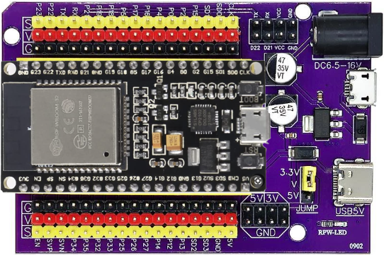
Pin Configuration and Descriptions

Pin Name Description
VIN Input voltage pin (7-12V) for powering the baseboard.
3V3 Regulated 3.3V output from the onboard voltage regulator.
GND Ground pin.
GPIOx General-purpose input/output pins. Supports digital I/O, PWM, ADC, etc.
TXD/RXD UART communication pins for serial data transmission and reception.
SDA/SCL I2C communication pins for connecting sensors and peripherals.
EN Enable pin. Pulling low resets the ESP32.
BOOT Boot mode selection pin. Used for flashing firmware.

Usage Instructions

How to Use the ESP32 on Baseboard in a Circuit

  1. Powering the Board:

    • Connect the baseboard to a USB power source (5V) or use the VIN pin with a 7-12V power supply.
    • Ensure the power source provides sufficient current (at least 500 mA).
  2. Connecting Peripherals:

    • Use the GPIO pins to connect sensors, actuators, or other devices. Refer to the pinout diagram for specific pin functions.
    • For analog sensors, connect them to ADC pins (e.g., GPIO32, GPIO33).
  3. Programming the ESP32:

    • Install the Arduino IDE or ESP-IDF (Espressif IoT Development Framework).
    • Add the ESP32 board package to the Arduino IDE via the Board Manager.
    • Connect the ESP32 to your computer using a USB cable.
    • Select the correct board and port in the IDE, then upload your code.
  4. Flashing Firmware:

    • Hold the BOOT button while pressing the EN button to enter firmware flashing mode.
    • Use the appropriate tools (e.g., esptool.py) to upload firmware.

Important Considerations and Best Practices

  • Voltage Levels: Ensure all connected peripherals operate at 3.3V logic levels to avoid damaging the ESP32.
  • Power Supply: Use a stable power source to prevent unexpected resets or performance issues.
  • Deep Sleep Mode: Utilize the deep sleep mode to reduce power consumption in battery-powered applications.
  • GPIO Limitations: Some GPIO pins have specific functions or limitations (e.g., GPIO0 is used for boot mode). Refer to the datasheet for details.

Example Code for Arduino UNO Integration

The following example demonstrates how to use the ESP32 to read data from a DHT11 temperature and humidity sensor and send it to a serial monitor.

#include <DHT.h>

// Define the DHT sensor type and pin
#define DHTPIN 4       // GPIO4 is connected to the DHT11 data pin
#define DHTTYPE DHT11  // DHT11 sensor

DHT dht(DHTPIN, DHTTYPE);

void setup() {
  Serial.begin(115200);  // Initialize serial communication
  dht.begin();           // Initialize the DHT sensor
  Serial.println("DHT11 Sensor Test");
}

void loop() {
  delay(2000);  // Wait 2 seconds between readings

  // Read temperature and humidity values
  float humidity = dht.readHumidity();
  float temperature = dht.readTemperature();

  // Check if the readings are valid
  if (isnan(humidity) || isnan(temperature)) {
    Serial.println("Failed to read from DHT sensor!");
    return;
  }

  // Print the readings to the serial monitor
  Serial.print("Humidity: ");
  Serial.print(humidity);
  Serial.print("%  Temperature: ");
  Serial.print(temperature);
  Serial.println("°C");
}

Troubleshooting and FAQs

Common Issues and Solutions

  1. ESP32 Not Detected by Computer:

    • Ensure the USB cable is functional and supports data transfer.
    • Install the correct USB-to-serial driver for your operating system.
  2. Upload Fails with Timeout Error:

    • Check that the correct board and port are selected in the Arduino IDE.
    • Hold the BOOT button while uploading the code.
  3. Unstable Wi-Fi Connection:

    • Verify the Wi-Fi credentials in your code.
    • Ensure the ESP32 is within range of the Wi-Fi router.
  4. GPIO Pin Not Working:

    • Confirm the pin is not reserved for special functions (e.g., GPIO0, GPIO2).
    • Check for wiring issues or incorrect pin assignments in the code.

FAQs

Q: Can I power the ESP32 on Baseboard with a battery?
A: Yes, you can use a 3.7V LiPo battery with a suitable voltage regulator or connect a 7-12V battery to the VIN pin.

Q: How do I reset the ESP32?
A: Press the EN button on the baseboard to reset the ESP32.

Q: Can I use the ESP32 with other IDEs besides Arduino?
A: Yes, the ESP32 is compatible with ESP-IDF, PlatformIO, and other development environments.

Q: What is the maximum number of devices I can connect via Bluetooth?
A: The ESP32 supports up to 7 Bluetooth devices simultaneously, depending on the application.