How to Use 2S 18650 Li-Ion BMS: Examples, Pinouts, and Specs
2S 18650 Li-Ion BMS Documentation
1. Introduction
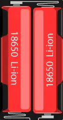
The 2S 18650 Li-Ion BMS (Battery Management System) is a compact and efficient module designed to manage and protect two 18650 lithium-ion cells connected in series. This BMS ensures the safe operation of the battery pack by providing critical features such as overcharge protection, over-discharge protection, and short-circuit protection. It is an essential component for building reliable and safe battery packs for various applications.
Common Applications
- DIY power banks
- Portable electronic devices
- Solar energy storage systems
- Electric bicycles and scooters
- Robotics and IoT projects
- Uninterruptible Power Supplies (UPS)
2. Technical Specifications
The following table outlines the key technical details of the 2S 18650 Li-Ion BMS:
| Parameter | Value |
|---|---|
| Battery Configuration | 2 cells in series (2S) |
| Input Voltage Range | 7.4V to 8.4V |
| Overcharge Protection | 4.25V ± 0.05V per cell |
| Over-discharge Protection | 2.5V ± 0.1V per cell |
| Maximum Continuous Current | 10A |
| Short-Circuit Protection | Yes |
| Balance Function | No |
| Operating Temperature | -40°C to 85°C |
| Dimensions | ~45mm x 15mm x 3mm |
Pin Configuration and Descriptions
| Pin Name | Description |
|---|---|
| B+ | Positive terminal of the battery pack (connect to the positive terminal of the first cell). |
| B- | Negative terminal of the battery pack (connect to the negative terminal of the second cell). |
| P+ | Positive output terminal (connect to the load or charging circuit). |
| P- | Negative output terminal (connect to the load or charging circuit). |
3. Usage Instructions
Connecting the 2S 18650 BMS
Prepare the Battery Pack: Ensure you have two 18650 lithium-ion cells with similar capacity and charge levels. Connect them in series:
- The positive terminal of the first cell connects to the negative terminal of the second cell.
- The remaining terminals are the pack's overall positive and negative terminals.
Connect the BMS:
- Connect the B+ pin to the positive terminal of the battery pack.
- Connect the B- pin to the negative terminal of the battery pack.
- Connect the P+ and P- pins to the load or charging circuit.
Verify Connections: Double-check all connections to ensure they are secure and correct. Incorrect wiring can damage the BMS or the battery pack.
Important Considerations
- Cell Matching: Use cells with the same capacity, internal resistance, and charge level to ensure balanced operation.
- Heat Dissipation: Avoid placing the BMS in an enclosed space without proper ventilation, as it may generate heat during operation.
- Charging Voltage: Use a charger designed for 2S lithium-ion packs (8.4V output) to avoid overcharging.
- Load Current: Ensure the load does not exceed the maximum continuous current rating (10A).
4. Example Application with Arduino UNO
The 2S 18650 BMS can be used to power an Arduino UNO in portable projects. Below is an example of how to connect the BMS to an Arduino UNO and monitor the battery voltage.
Circuit Diagram
- Connect the P+ and P- terminals of the BMS to the Arduino's VIN and GND pins, respectively.
- Use a voltage divider circuit to measure the battery voltage with an analog pin on the Arduino.
Arduino Code Example
// Example code to monitor battery voltage using Arduino UNO
// Ensure the voltage divider output does not exceed 5V (Arduino's ADC limit)

const int voltagePin = A0; // Analog pin connected to the voltage divider
const float R1 = 10000.0; // Resistor value in the voltage divider (10k ohms)
const float R2 = 10000.0; // Resistor value in the voltage divider (10k ohms)
const float referenceVoltage = 5.0; // Arduino's ADC reference voltage
const int adcResolution = 1023; // 10-bit ADC resolution

void setup() {
  Serial.begin(9600); // Initialize serial communication
}

void loop() {
  int adcValue = analogRead(voltagePin); // Read the ADC value
  float voltage = (adcValue * referenceVoltage / adcResolution) * ((R1 + R2) / R2);

  // Print the battery voltage to the Serial Monitor
  Serial.print("Battery Voltage: ");
  Serial.print(voltage);
  Serial.println(" V");

  delay(1000); // Wait for 1 second before the next reading
}
Notes:
- Use appropriate resistor values in the voltage divider to scale the battery voltage to a safe range for the Arduino's ADC.
- The code assumes a 10kΩ:10kΩ voltage divider, which scales the maximum battery voltage (8.4V) to 4.2V.
5. Troubleshooting and FAQs
Common Issues and Solutions
| Issue | Possible Cause | Solution |
|---|---|---|
| BMS not powering the load | Incorrect wiring or loose connections | Verify all connections and ensure proper wiring. |
| Battery pack not charging | Charger voltage not compatible with 2S pack | Use a charger with an 8.4V output. |
| Overheating during operation | Exceeding maximum current rating | Reduce the load current or improve ventilation. |
| Cells discharging unevenly | Mismatched cells in the pack | Use cells with similar capacity and charge level. |
Frequently Asked Questions
Q1: Can I use this BMS for a single 18650 cell?
A1: No, this BMS is specifically designed for two cells in series (2S configuration). For a single cell, use a 1S BMS.
Q2: Does this BMS support cell balancing?
A2: No, this BMS does not include a cell balancing function. Ensure the cells are balanced before use.
Q3: Can I use this BMS for a 3S or higher battery pack?
A3: No, this BMS is only suitable for 2S configurations. For higher configurations, use a BMS designed for the specific number of cells.
Q4: What happens if I exceed the maximum current rating?
A4: The BMS will trigger short-circuit protection and disconnect the load to prevent damage.
This documentation provides a comprehensive guide to using the 2S 18650 Li-Ion BMS safely and effectively. For further assistance, consult online resources or forums dedicated to battery management systems.
Explore Projects Built with 2S 18650 Li-Ion BMS


Explore Projects Built with 2S 18650 Li-Ion BMS