How to Use Adafruit MAX31865 RTD Sensor Breakout: Examples, Pinouts, and Specs
Introduction
The Adafruit MAX31865 RTD Sensor Breakout is an electronic component designed to interface with an RTD sensor, providing precise temperature measurements. RTDs, or Resistance Temperature Detectors, are sensors used to measure temperature by correlating the resistance of the RTD element with temperature. The MAX31865 breakout board simplifies the process of reading temperatures from an RTD by handling the necessary amplification and analog-to-digital conversion.
Explore Projects Built with Adafruit MAX31865 RTD Sensor Breakout
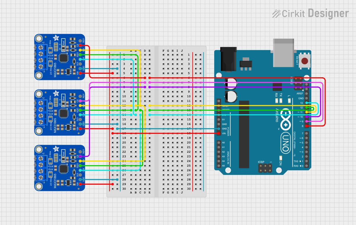
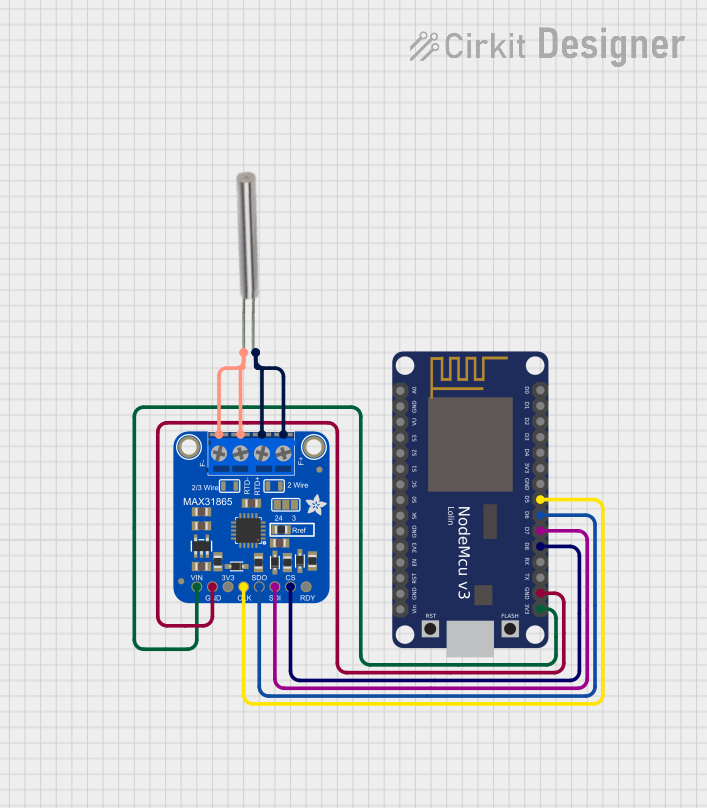
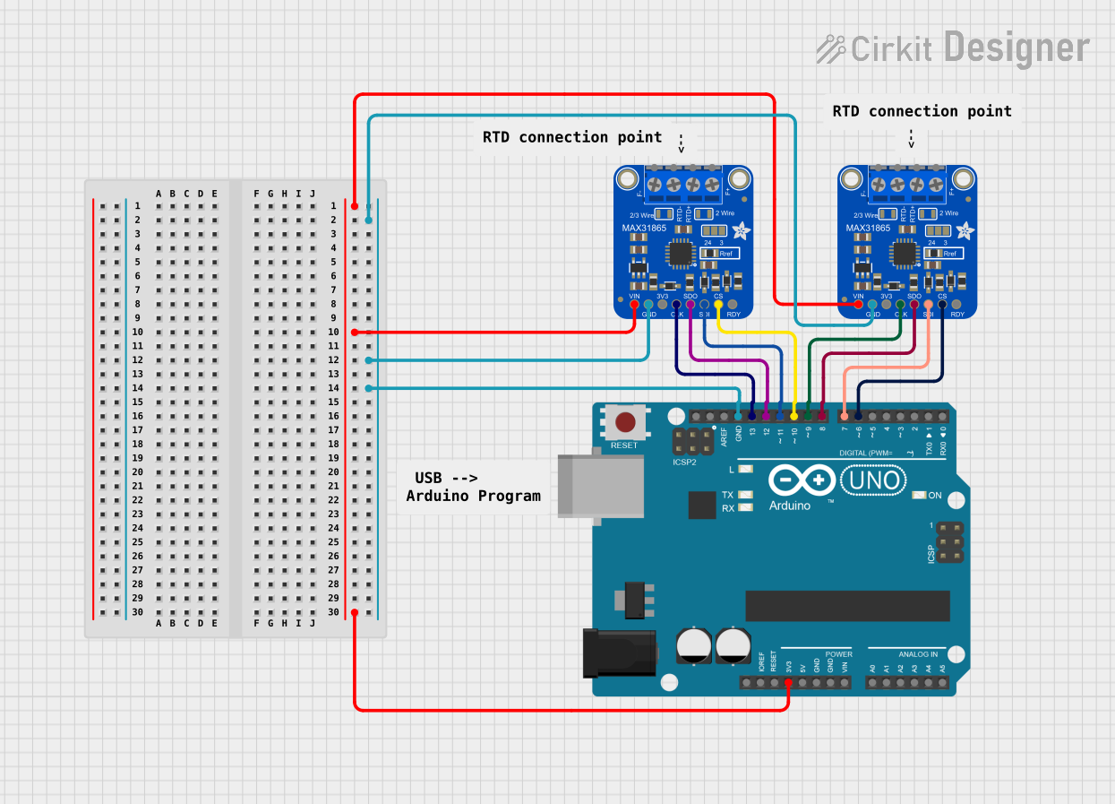
Explore Projects Built with Adafruit MAX31865 RTD Sensor Breakout
Common Applications and Use Cases
- Industrial temperature monitoring
- Precision temperature control systems
- Environmental monitoring
- Laboratory and research
- HVAC systems
Technical Specifications
Key Technical Details
- Supply Voltage: 3.3V to 5V
- Current Consumption: 1.3mA (typical)
- Temperature Resolution: 0.03125°C
- Supports 2, 3, or 4 wire RTDs
- Onboard reverse voltage protection
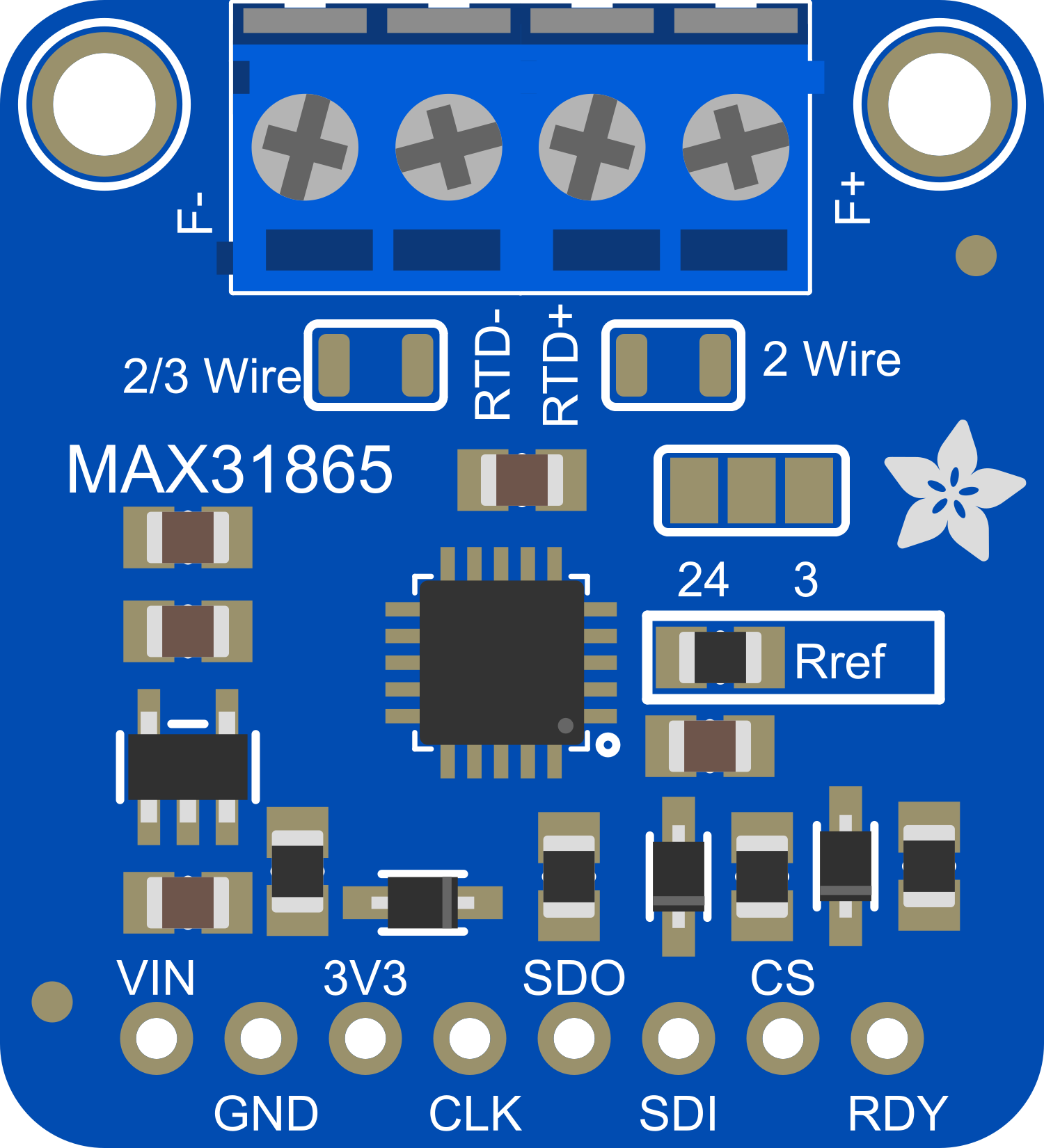
Pin Configuration and Descriptions
| Pin | Description |
|---|---|
| VIN | Supply voltage (3.3V to 5V) |
| GND | Ground |
| SCK | Serial Clock Input for SPI |
| MISO | Master In Slave Out for SPI |
| MOSI | Master Out Slave In for SPI |
| CS | Chip Select for SPI |
| RDY | Ready pin to indicate new data is available |
Usage Instructions
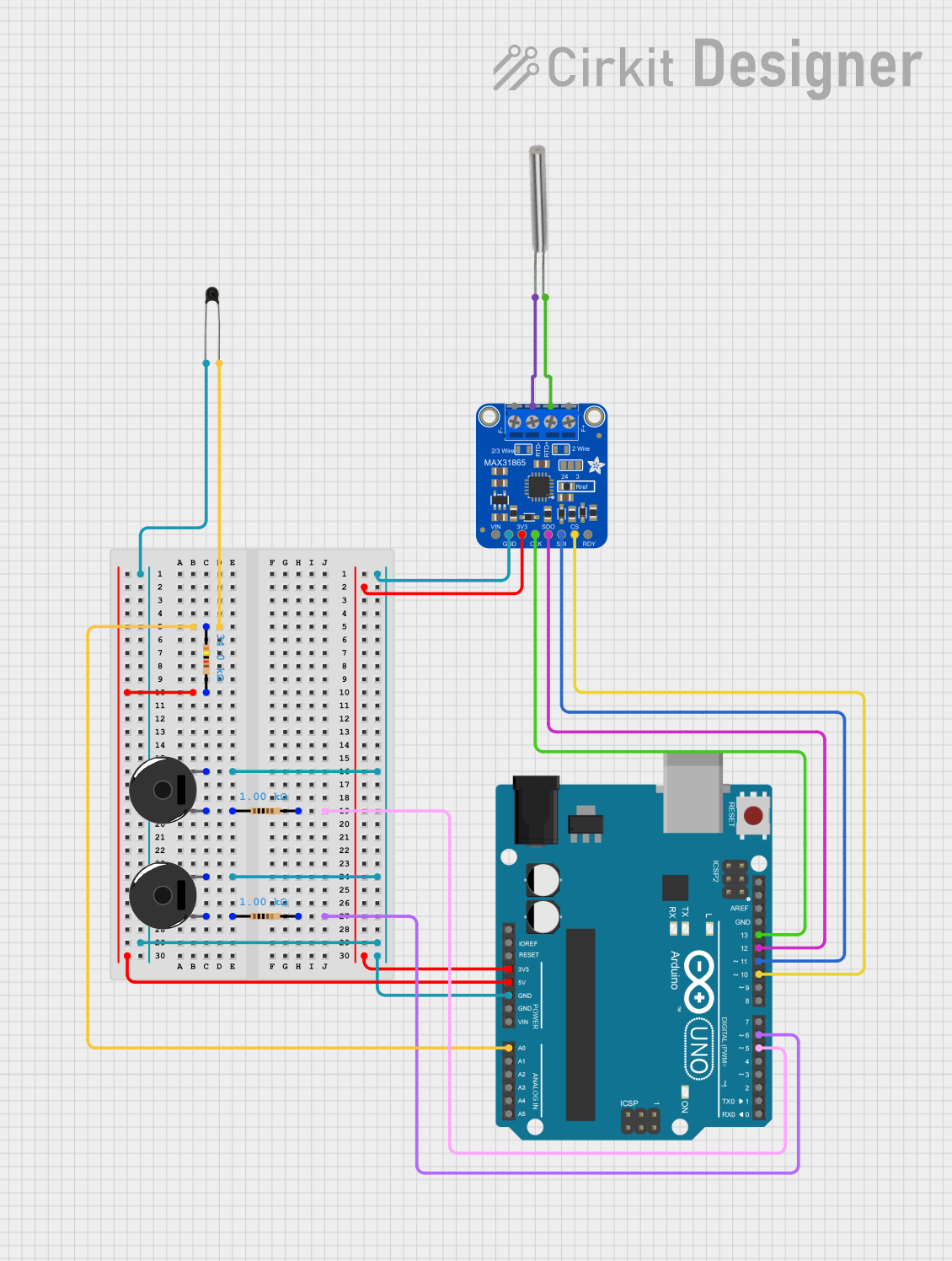
Connecting the MAX31865 to a Circuit
- Connect the VIN pin to a 3.3V or 5V power supply.
- Connect the GND pin to the ground of the power supply.
- Interface the SCK, MISO, MOSI, and CS pins with the corresponding SPI pins on your microcontroller.
- Connect the RTD sensor to the RTD+ and RTD- pins on the breakout board.
- If using a 3-wire RTD, connect the third wire to the RTD+ pin through a jumper.
Important Considerations and Best Practices
- Ensure that the power supply voltage matches the requirements of the breakout board.
- Use short and thick wires for RTD connections to minimize resistance changes due to wire length.
- Keep the breakout board away from heat sources to avoid affecting the readings.
- Use proper ESD precautions when handling the breakout board to prevent damage.
Example Code for Arduino UNO
#include <SPI.h>
#include <Adafruit_MAX31865.h>

// Use software SPI: CS, DI, DO, CLK
Adafruit_MAX31865 max = Adafruit_MAX31865(10, 11, 12, 13);
// Use hardware SPI, just pass in the CS pin
//Adafruit_MAX31865 max = Adafruit_MAX31865(10);

void setup() {
  Serial.begin(115200);
  Serial.println("Adafruit MAX31865 PT100 Sensor Test!");

  max.begin(MAX31865_3WIRE); // set to 2WIRE or 4WIRE as needed
}

void loop() {
  uint16_t rtd = max.readRTD();

  Serial.print("RTD value: "); Serial.println(rtd);
  float ratio = rtd;
  ratio /= 32768;
  Serial.print("Ratio = "); Serial.println(ratio,8);
  Serial.print("Resistance = "); Serial.println(RREF*ratio,8);
  Serial.print("Temperature = "); Serial.println(max.temperature(RNOMINAL, RREF));

  // Check and print any faults
  uint8_t fault = max.readFault();
  if (fault) {
    Serial.print("Fault 0x"); Serial.println(fault, HEX);
    if (fault & MAX31865_FAULT_HIGHTHRESH) {
      Serial.println("RTD High Threshold");
    }
    if (fault & MAX31865_FAULT_LOWTHRESH) {
      Serial.println("RTD Low Threshold");
    }
    if (fault & MAX31865_FAULT_REFINLOW) {
      Serial.println("REFIN- > 0.85 x Bias");
    }
    if (fault & MAX31865_FAULT_REFINHIGH) {
      Serial.println("REFIN- < 0.85 x Bias - FORCE- open");
    }
    if (fault & MAX31865_FAULT_RTDINLOW) {
      Serial.println("RTDIN- < 0.85 x Bias - FORCE- open");
    }
    if (fault & MAX31865_FAULT_OVUV) {
      Serial.println("Under/Over voltage");
    }
    max.clearFault();
  }
  delay(1000);
}
Troubleshooting and FAQs
Common Issues
- Incorrect Temperature Readings: Ensure that the RTD wires are connected properly and that the correct wire configuration (2, 3, or 4 wire) is set in the code.
- No Data or Communication Errors: Check the SPI connections and ensure that the correct pins are used for SCK, MISO, MOSI, and CS.
- Device Not Powering On: Verify that the power supply is within the specified voltage range and that the VIN and GND connections are secure.
Solutions and Tips for Troubleshooting
- Double-check wiring and solder joints for any loose connections or shorts.
- Use the
readFault()function to check for specific errors and address them as indicated by the MAX31865 datasheet. - Ensure that the breakout board is not placed near heat-generating components that could affect the temperature readings.
FAQs
Q: Can I use the MAX31865 with a PT1000 RTD? A: Yes, the MAX31865 can be configured to work with PT1000 RTDs by adjusting the reference resistor value in the code.
Q: How accurate is the MAX31865 breakout board? A: The MAX31865 offers a temperature resolution of 0.03125°C, but the overall accuracy depends on the RTD sensor and the system design.
Q: What is the maximum temperature the MAX31865 can measure? A: The maximum temperature is determined by the RTD sensor used. PT100 sensors typically measure up to 850°C, but always refer to the sensor's datasheet for its specific range.
Q: How do I calibrate the MAX31865 breakout board? A: Calibration involves comparing the readings from the MAX31865 with a known temperature reference and adjusting the reference resistor value or using software compensation to correct any discrepancies.