Cirkit Designer Logo
Cirkit Designer
Your all-in-one circuit design IDE
Home / 
Component Documentation

How to Use KY-009: Examples, Pinouts, and Specs

Image of KY-009
Cirkit Designer LogoDesign with KY-009 in Cirkit Designer

Introduction

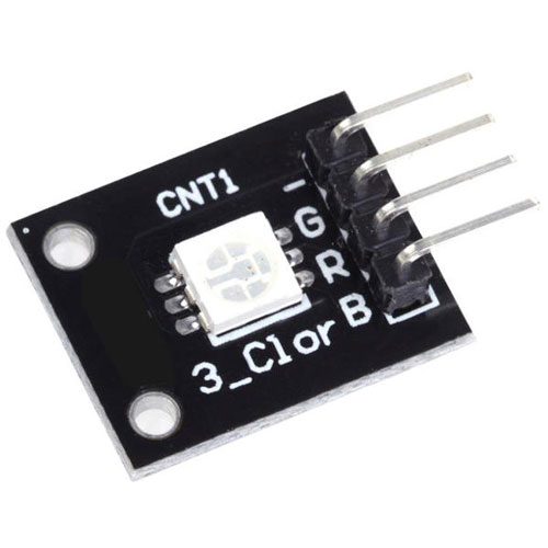
The KY-009 is a simple RGB LED module manufactured by Arduino (Part ID: 2). This module features a Red-Green-Blue (RGB) LED that allows users to control the color and brightness of the light using Pulse Width Modulation (PWM). It is a versatile component commonly used in projects requiring visual indicators, decorative lighting, or color-based feedback systems.

Explore Projects Built with KY-009

Use Cirkit Designer to design, explore, and prototype these projects online. Some projects support real-time simulation. Click "Open Project" to start designing instantly!
Arduino Nano Joystick-Controlled Bluetooth Module with Battery Power
Image of padelpro transmitter: A project utilizing KY-009 in a practical application
This circuit is a wireless joystick controller that uses an Arduino Nano to read analog signals from a KY-023 Dual Axis Joystick Module and transmits the data via an HC-05 Bluetooth Module. The system is powered by a 18650 Li-Ion battery with a rocker switch for power control.
Cirkit Designer LogoOpen Project in Cirkit Designer
Arduino Nano-Based Wireless Joystick and Motion Controller
Image of hand gesture: A project utilizing KY-009 in a practical application
This circuit features an Arduino Nano microcontroller interfaced with an HC-05 Bluetooth module, an MPU-6050 accelerometer/gyroscope, and a KY-023 Dual Axis Joystick Module. The Arduino Nano is powered by a 9V battery through a rocker switch and communicates with the HC-05 for Bluetooth connectivity, reads joystick positions from the KY-023 module via analog inputs, and communicates with the MPU-6050 over I2C to capture motion data. The circuit is likely designed for wireless control and motion sensing applications, such as a remote-controlled robot or a game controller.
Cirkit Designer LogoOpen Project in Cirkit Designer
ESP32-Based Security System with RFID and Laser Tripwire
Image of CPE doorlock system: A project utilizing KY-009 in a practical application
This circuit is designed for a comprehensive security and access control system with motion detection, access via RFID, and a break-beam sensor. It includes a solenoid lock controlled by a relay, visual and audible alerts, and a robust power management system with solar and battery backup to ensure uninterrupted operation.
Cirkit Designer LogoOpen Project in Cirkit Designer
Arduino Nano Controlled Joystick with NRF24L01 Wireless Communication
Image of drone remote: A project utilizing KY-009 in a practical application
This circuit features an Arduino Nano interfaced with two KY-023 Dual Axis Joystick Modules and an NRF24L01 wireless transceiver module. The joysticks provide X and Y axis inputs to the Arduino, which reads these analog signals and a button state, then transmits a message wirelessly via the NRF24L01. The circuit is likely used for remote control applications, with the Arduino processing joystick inputs and handling wireless communication to send control signals to a receiver.
Cirkit Designer LogoOpen Project in Cirkit Designer

Explore Projects Built with KY-009

Use Cirkit Designer to design, explore, and prototype these projects online. Some projects support real-time simulation. Click "Open Project" to start designing instantly!
Image of padelpro transmitter: A project utilizing KY-009 in a practical application
Arduino Nano Joystick-Controlled Bluetooth Module with Battery Power
This circuit is a wireless joystick controller that uses an Arduino Nano to read analog signals from a KY-023 Dual Axis Joystick Module and transmits the data via an HC-05 Bluetooth Module. The system is powered by a 18650 Li-Ion battery with a rocker switch for power control.
Cirkit Designer LogoOpen Project in Cirkit Designer
Image of hand gesture: A project utilizing KY-009 in a practical application
Arduino Nano-Based Wireless Joystick and Motion Controller
This circuit features an Arduino Nano microcontroller interfaced with an HC-05 Bluetooth module, an MPU-6050 accelerometer/gyroscope, and a KY-023 Dual Axis Joystick Module. The Arduino Nano is powered by a 9V battery through a rocker switch and communicates with the HC-05 for Bluetooth connectivity, reads joystick positions from the KY-023 module via analog inputs, and communicates with the MPU-6050 over I2C to capture motion data. The circuit is likely designed for wireless control and motion sensing applications, such as a remote-controlled robot or a game controller.
Cirkit Designer LogoOpen Project in Cirkit Designer
Image of CPE doorlock system: A project utilizing KY-009 in a practical application
ESP32-Based Security System with RFID and Laser Tripwire
This circuit is designed for a comprehensive security and access control system with motion detection, access via RFID, and a break-beam sensor. It includes a solenoid lock controlled by a relay, visual and audible alerts, and a robust power management system with solar and battery backup to ensure uninterrupted operation.
Cirkit Designer LogoOpen Project in Cirkit Designer
Image of drone remote: A project utilizing KY-009 in a practical application
Arduino Nano Controlled Joystick with NRF24L01 Wireless Communication
This circuit features an Arduino Nano interfaced with two KY-023 Dual Axis Joystick Modules and an NRF24L01 wireless transceiver module. The joysticks provide X and Y axis inputs to the Arduino, which reads these analog signals and a button state, then transmits a message wirelessly via the NRF24L01. The circuit is likely used for remote control applications, with the Arduino processing joystick inputs and handling wireless communication to send control signals to a receiver.
Cirkit Designer LogoOpen Project in Cirkit Designer

Common Applications and Use Cases

  • Visual indicators for electronic projects
  • Decorative lighting in DIY projects
  • Color-coded feedback systems
  • Educational projects to demonstrate PWM and LED control
  • Mood lighting or ambient light systems

Technical Specifications

The KY-009 module is designed for ease of use and compatibility with microcontrollers like the Arduino UNO. Below are its key technical details:

Key Technical Details

  • Operating Voltage: 3.3V to 5V
  • Current Consumption: ~20mA per LED channel (Red, Green, Blue)
  • LED Type: Common cathode RGB LED
  • Control Method: PWM for each color channel
  • Dimensions: 18.5mm x 15mm x 7mm (approx.)

Pin Configuration and Descriptions

The KY-009 module has 4 pins, as described in the table below:

Pin Name Description
1 R (Red) Connect to a PWM-capable pin on the microcontroller to control the red channel.
2 G (Green) Connect to a PWM-capable pin on the microcontroller to control the green channel.
3 B (Blue) Connect to a PWM-capable pin on the microcontroller to control the blue channel.
4 GND (Ground) Connect to the ground of the power supply or microcontroller.

Usage Instructions

The KY-009 module is straightforward to use in circuits. Below are the steps and best practices for integrating it into your project.

How to Use the KY-009 in a Circuit

  1. Connect the Pins:
    • Connect the R, G, and B pins to PWM-capable pins on your microcontroller (e.g., Arduino UNO).
    • Connect the GND pin to the ground of your power supply or microcontroller.
  2. Write a Program:
    • Use PWM signals to control the brightness of each color channel (Red, Green, Blue).
    • By varying the duty cycle of the PWM signals, you can mix colors to create a wide range of hues.
  3. Power the Circuit:
    • Ensure the module is powered within its operating voltage range (3.3V to 5V).

Important Considerations and Best Practices

  • Resistors: Use current-limiting resistors (220Ω to 330Ω) on the R, G, and B pins to prevent excessive current draw and protect the LED.
  • PWM Pins: Ensure the microcontroller pins connected to R, G, and B support PWM functionality.
  • Heat Management: Avoid running the LED at maximum brightness for extended periods to prevent overheating.
  • Power Supply: Use a stable power supply to avoid flickering or inconsistent brightness.

Example Code for Arduino UNO

Below is an example Arduino sketch to control the KY-009 module and create a color-fading effect:

// Define the PWM pins connected to the KY-009 module
const int redPin = 9;   // Red channel connected to pin 9
const int greenPin = 10; // Green channel connected to pin 10
const int bluePin = 11;  // Blue channel connected to pin 11

void setup() {
  // Set the RGB pins as output
  pinMode(redPin, OUTPUT);
  pinMode(greenPin, OUTPUT);
  pinMode(bluePin, OUTPUT);
}

void loop() {
  // Gradually increase and decrease brightness of each color
  for (int i = 0; i <= 255; i++) {
    analogWrite(redPin, i);   // Increase red brightness
    analogWrite(greenPin, 255 - i); // Decrease green brightness
    analogWrite(bluePin, i / 2);    // Adjust blue brightness
    delay(10); // Small delay for smooth fading
  }
}

Troubleshooting and FAQs

Common Issues and Solutions

  1. LED Not Lighting Up:

    • Cause: Incorrect wiring or missing ground connection.
    • Solution: Double-check the connections, ensuring the GND pin is properly connected.
  2. Incorrect Colors or No Color Mixing:

    • Cause: PWM pins not used or incorrect pin assignments in the code.
    • Solution: Verify that the R, G, and B pins are connected to PWM-capable pins on the microcontroller. Update the pin assignments in the code if necessary.
  3. Flickering or Inconsistent Brightness:

    • Cause: Unstable power supply or insufficient current-limiting resistors.
    • Solution: Use a stable power source and ensure appropriate resistors are used on the R, G, and B pins.
  4. Overheating:

    • Cause: Running the LED at maximum brightness for extended periods.
    • Solution: Reduce the duty cycle of the PWM signals or add a heat sink if necessary.

FAQs

Q1: Can I use the KY-009 with a 3.3V microcontroller?
A1: Yes, the KY-009 is compatible with both 3.3V and 5V systems. Ensure the PWM signals are within the operating voltage range.

Q2: How do I create specific colors with the KY-009?
A2: By adjusting the PWM duty cycles for the R, G, and B pins, you can mix colors. For example:

  • Red: analogWrite(redPin, 255); analogWrite(greenPin, 0); analogWrite(bluePin, 0);
  • Green: analogWrite(redPin, 0); analogWrite(greenPin, 255); analogWrite(bluePin, 0);
  • Blue: analogWrite(redPin, 0); analogWrite(greenPin, 0); analogWrite(bluePin, 255);

Q3: Do I need external components to use the KY-009?
A3: Yes, it is recommended to use current-limiting resistors (220Ω to 330Ω) to protect the LED from excessive current.