How to Use zocaloDWM: Examples, Pinouts, and Specs
Introduction
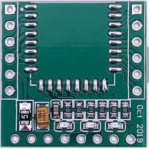
The zocaloDWM is a specialized socket designed by KNKL for securely mounting and connecting DWM (Data Wireless Module) components. This socket simplifies the integration of DWM modules into electronic circuits by providing a reliable interface for communication and power supply. Its robust design ensures stable connections, making it ideal for both prototyping and production environments.
Explore Projects Built with zocaloDWM


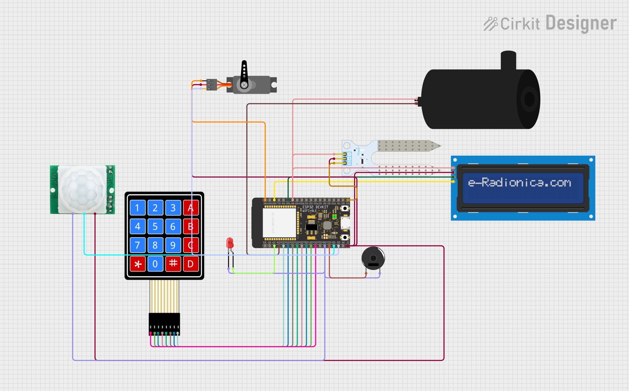
Explore Projects Built with zocaloDWM
Common Applications and Use Cases
- IoT Devices: Used in wireless communication modules for smart devices.
- Prototyping: Simplifies the testing and development of DWM-based systems.
- Embedded Systems: Provides a reliable connection for DWM modules in embedded applications.
- Industrial Automation: Facilitates wireless communication in industrial control systems.
Technical Specifications
Key Technical Details
- Manufacturer: KNKL
- Supported Module Type: DWM (Data Wireless Module)
- Number of Pins: 16
- Pin Pitch: 2.54 mm (standard breadboard-compatible spacing)
- Operating Voltage: 3.3V to 5V (dependent on the DWM module specifications)
- Current Rating: Up to 500 mA per pin
- Material: High-temperature thermoplastic with gold-plated contacts
- Operating Temperature: -40°C to 85°C
- Mounting Type: Through-hole or surface-mount (varies by model)
Pin Configuration and Descriptions
The zocaloDWM socket has 16 pins, which are typically mapped to the corresponding pins of the DWM module. Below is the standard pin configuration:
| Pin Number | Pin Name | Description |
|---|---|---|
| 1 | VCC | Power supply input (3.3V or 5V) |
| 2 | GND | Ground connection |
| 3 | TX | Transmit data (UART communication) |
| 4 | RX | Receive data (UART communication) |
| 5 | RESET | Module reset pin |
| 6 | EN | Enable pin (activates the module) |
| 7 | GPIO1 | General-purpose I/O pin 1 |
| 8 | GPIO2 | General-purpose I/O pin 2 |
| 9 | GPIO3 | General-purpose I/O pin 3 |
| 10 | GPIO4 | General-purpose I/O pin 4 |
| 11 | SPI_MOSI | SPI Master Out Slave In |
| 12 | SPI_MISO | SPI Master In Slave Out |
| 13 | SPI_SCK | SPI Clock |
| 14 | SPI_CS | SPI Chip Select |
| 15 | ADC_IN | Analog-to-digital converter input |
| 16 | NC | Not connected (reserved for future use) |
Note: Pin assignments may vary depending on the specific DWM module. Always refer to the module's datasheet for compatibility.
Usage Instructions
How to Use the zocaloDWM in a Circuit
- Mounting the Socket:
- Solder the zocaloDWM socket onto a PCB or insert it into a breadboard.
- Ensure proper alignment of the pins to avoid misconnection.
- Inserting the DWM Module:
- Carefully align the DWM module with the socket.
- Gently press the module into the socket until it is securely seated.
- Connecting Power and Communication Lines:
- Connect the VCC and GND pins to the appropriate power supply.
- Use the TX and RX pins for UART communication or the SPI pins for SPI communication, depending on your application.
- Programming and Testing:
- If using a microcontroller (e.g., Arduino UNO), connect the relevant pins to the microcontroller and upload the necessary code.
Important Considerations and Best Practices
- Voltage Compatibility: Ensure the power supply voltage matches the requirements of the DWM module.
- Static Protection: Handle the socket and module with care to avoid damage from electrostatic discharge (ESD).
- Pin Mapping: Double-check the pin mapping of the DWM module to ensure proper connections.
- Secure Mounting: For long-term use, ensure the socket is securely soldered to the PCB to prevent loose connections.
Example: Using zocaloDWM with Arduino UNO
Below is an example of how to connect a DWM module via the zocaloDWM socket to an Arduino UNO for UART communication:
Circuit Connections
- zocaloDWM Pin 1 (VCC) → Arduino 3.3V
- zocaloDWM Pin 2 (GND) → Arduino GND
- zocaloDWM Pin 3 (TX) → Arduino Pin 10 (RX)
- zocaloDWM Pin 4 (RX) → Arduino Pin 11 (TX)
Arduino Code
// Example code for communicating with a DWM module via zocaloDWM socket
#include <SoftwareSerial.h>

// Define RX and TX pins for SoftwareSerial
SoftwareSerial DWMSerial(10, 11); // RX = Pin 10, TX = Pin 11

void setup() {
  Serial.begin(9600); // Start Serial Monitor communication
  DWMSerial.begin(9600); // Start communication with DWM module

  Serial.println("Initializing DWM module...");
  DWMSerial.println("AT"); // Send an AT command to test communication
}

void loop() {
  // Check if data is available from the DWM module
  if (DWMSerial.available()) {
    String data = DWMSerial.readString();
    Serial.println("Received from DWM: " + data);
  }

  // Send data to the DWM module
  if (Serial.available()) {
    String command = Serial.readString();
    DWMSerial.println(command);
  }
}
Note: Adjust the baud rate (
9600) as per the DWM module's specifications.
Troubleshooting and FAQs
Common Issues and Solutions
DWM Module Not Powering On:
- Cause: Incorrect power supply voltage.
- Solution: Verify that the VCC pin is receiving the correct voltage (3.3V or 5V).
No Communication with the DWM Module:
- Cause: Misaligned or loose connections.
- Solution: Ensure the DWM module is properly seated in the socket and all connections are secure.
Data Transmission Errors:
- Cause: Incorrect baud rate or mismatched communication settings.
- Solution: Check the DWM module's datasheet for the correct baud rate and update the code accordingly.
Overheating Socket:
- Cause: Excessive current draw or short circuit.
- Solution: Verify the circuit for shorts and ensure the current does not exceed 500 mA per pin.
FAQs
Q: Can the zocaloDWM be used with other types of modules?
A: The zocaloDWM is specifically designed for DWM modules. Compatibility with other modules depends on pin alignment and electrical specifications.Q: Is the socket reusable?
A: Yes, the zocaloDWM socket is designed for repeated use, making it ideal for prototyping.Q: What is the maximum insertion/removal cycle rating?
A: The socket is rated for up to 1000 insertion/removal cycles under normal operating conditions.
By following this documentation, users can effectively integrate the zocaloDWM socket into their projects, ensuring reliable performance and ease of use.