Cirkit Designer Logo
Cirkit Designer
Your all-in-one circuit design IDE
Home / 
Component Documentation

How to Use CAN Bus Shield: Examples, Pinouts, and Specs

Image of CAN Bus Shield
Cirkit Designer LogoDesign with CAN Bus Shield in Cirkit Designer

Introduction

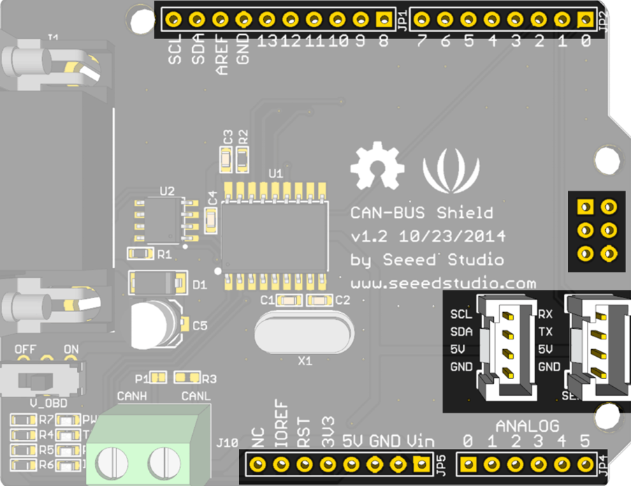
The CAN Bus Shield by SEEED is an expansion board designed to enable Arduino boards to communicate over a Controller Area Network (CAN). This shield is particularly useful for automotive and industrial applications where multiple microcontrollers need to communicate with each other efficiently without a host computer.

Common applications include:

  • Automotive diagnostics
  • Industrial automation systems
  • Robotics control systems
  • Data logging from various sensors

Explore Projects Built with CAN Bus Shield

Use Cirkit Designer to design, explore, and prototype these projects online. Some projects support real-time simulation. Click "Open Project" to start designing instantly!
Arduino Sensor Shield with I2C LCD and Bluetooth Interface
Image of wallE: A project utilizing CAN Bus Shield in a practical application
This circuit features an Arduino Sensor Shield v5.0 interfaced with an I2C LCD Display and an HC-05 Bluetooth Module. The LCD Display is connected for power, ground, and I2C communication, allowing it to display data or messages. The HC-05 Bluetooth Module is wired for serial communication with the Arduino Sensor Shield, enabling wireless data exchange with other Bluetooth-enabled devices.
Cirkit Designer LogoOpen Project in Cirkit Designer
Arduino Nano-Based Remote-Controlled Dual Motor System with LiPo Battery
Image of nano shield zkbm1: A project utilizing CAN Bus Shield in a practical application
This circuit is designed to control two GM25 DC motors using a ZK-BM1 10A motor driver, which is managed by a NANO Shield Board. The NANO Shield Board receives input signals from an R6FG receiver and is powered by an 11.1V LiPo battery.
Cirkit Designer LogoOpen Project in Cirkit Designer
Arduino Nano OBD-II Data Logger with TFT Display and CAN Bus Interface
Image of inzynierka: A project utilizing CAN Bus Shield in a practical application
This circuit is an OBD-II vehicle diagnostic interface that uses an Arduino Nano to communicate with a vehicle's CAN bus via an MCP2515 CAN controller. It includes a 7805 voltage regulator to step down the vehicle's 12V supply to 5V, powering the Arduino and other components, and a 1.44-inch TFT display for visual output. A pushbutton is also included for user interaction.
Cirkit Designer LogoOpen Project in Cirkit Designer
Arduino UNO WiFi CAN Bus Interface with Sensor/Actuator Module
Image of CAN : SN65HVD230 via NS-LS2(LevelConverter)2: A project utilizing CAN Bus Shield in a practical application
This circuit features two Arduino UNO R4 WiFi microcontrollers interfaced with NS-LS2 light sensors and CAN_SN65HVD230 CAN bus transceivers. The Arduinos are configured to read light intensity data from the NS-LS2 sensors and communicate with each other over a CAN network, likely for a distributed sensing application. Power distribution is managed with 3.3V and 5V connections to the respective components, and the ground connections are shared across the devices to complete the circuit.
Cirkit Designer LogoOpen Project in Cirkit Designer

Explore Projects Built with CAN Bus Shield

Use Cirkit Designer to design, explore, and prototype these projects online. Some projects support real-time simulation. Click "Open Project" to start designing instantly!
Image of wallE: A project utilizing CAN Bus Shield in a practical application
Arduino Sensor Shield with I2C LCD and Bluetooth Interface
This circuit features an Arduino Sensor Shield v5.0 interfaced with an I2C LCD Display and an HC-05 Bluetooth Module. The LCD Display is connected for power, ground, and I2C communication, allowing it to display data or messages. The HC-05 Bluetooth Module is wired for serial communication with the Arduino Sensor Shield, enabling wireless data exchange with other Bluetooth-enabled devices.
Cirkit Designer LogoOpen Project in Cirkit Designer
Image of nano shield zkbm1: A project utilizing CAN Bus Shield in a practical application
Arduino Nano-Based Remote-Controlled Dual Motor System with LiPo Battery
This circuit is designed to control two GM25 DC motors using a ZK-BM1 10A motor driver, which is managed by a NANO Shield Board. The NANO Shield Board receives input signals from an R6FG receiver and is powered by an 11.1V LiPo battery.
Cirkit Designer LogoOpen Project in Cirkit Designer
Image of inzynierka: A project utilizing CAN Bus Shield in a practical application
Arduino Nano OBD-II Data Logger with TFT Display and CAN Bus Interface
This circuit is an OBD-II vehicle diagnostic interface that uses an Arduino Nano to communicate with a vehicle's CAN bus via an MCP2515 CAN controller. It includes a 7805 voltage regulator to step down the vehicle's 12V supply to 5V, powering the Arduino and other components, and a 1.44-inch TFT display for visual output. A pushbutton is also included for user interaction.
Cirkit Designer LogoOpen Project in Cirkit Designer
Image of CAN : SN65HVD230 via NS-LS2(LevelConverter)2: A project utilizing CAN Bus Shield in a practical application
Arduino UNO WiFi CAN Bus Interface with Sensor/Actuator Module
This circuit features two Arduino UNO R4 WiFi microcontrollers interfaced with NS-LS2 light sensors and CAN_SN65HVD230 CAN bus transceivers. The Arduinos are configured to read light intensity data from the NS-LS2 sensors and communicate with each other over a CAN network, likely for a distributed sensing application. Power distribution is managed with 3.3V and 5V connections to the respective components, and the ground connections are shared across the devices to complete the circuit.
Cirkit Designer LogoOpen Project in Cirkit Designer

Technical Specifications

Key Technical Details

  • Operating Voltage: 5V (from Arduino Board)
  • CAN Controller: MCP2515, interfaced via SPI
  • CAN Transceiver: TJA1050
  • CAN Bus Speed: Up to 1 Mb/s
  • Oscillator Frequency: 16 MHz
  • Standard (11 bit) and Extended (29 bit) Data and Remote Frames

Pin Configuration and Descriptions

Pin Number Function Description
D2 INT Interrupt pin, signals the Arduino of incoming messages
D9 CS Chip Select for SPI communication with MCP2515
D10 Not Connected Reserved for future use
D11 MOSI SPI communication with MCP2515
D12 MISO SPI communication with MCP2515
D13 SCK SPI Clock
GND Ground Ground connection
VCC Power Supply 5V power supply from the Arduino

Usage Instructions

Connecting the Shield to an Arduino

  1. Power off your Arduino board.
  2. Align the shield's pins with the corresponding headers on the Arduino.
  3. Gently press down until the shield is firmly seated on the Arduino.

Initializing the CAN Bus Shield

Before using the shield, you need to initialize the CAN controller and set the desired baud rate for communication. Here's an example of how to do this using the MCP_CAN library:

#include <mcp_can.h>
#include <SPI.h>

// The SPI Chip Select pin for the CAN controller
const int SPI_CS_PIN = 9;

MCP_CAN CAN(SPI_CS_PIN); // Set CS pin for CAN controller

void setup() {
  Serial.begin(115200);

  // Initialize CAN bus at 500 kbps
  if (CAN_OK == CAN.begin(CAN_500KBPS)) {
    Serial.println("CAN Bus Shield initialized at 500 kbps.");
  } else {
    Serial.println("CAN Bus Shield initialization failed.");
  }
}

void loop() {
  // Code to send and receive data goes here
}

Sending CAN Messages

To send data over the CAN bus, you can use the sendMsgBuf function provided by the MCP_CAN library:

unsigned char message[8] = {0x00, 0x01, 0x02, 0x03, 0x04, 0x05, 0x06, 0x07};

// Send a standard frame with ID 0x100 and length of 8 bytes
CAN.sendMsgBuf(0x100, 0, 8, message);

Receiving CAN Messages

To receive data, you can use the readMsgBuf and checkReceive functions:

unsigned char len = 0;
unsigned char buf[8];

if (CAN_MSGAVAIL == CAN.checkReceive()) {
  CAN.readMsgBuf(&len, buf); // Read data: len = data length, buf = data byte(s)
  unsigned long canId = CAN.getCanId();

  Serial.print("Message received with ID: ");
  Serial.print(canId, HEX);
  Serial.print(" Data: ");
  for (int i = 0; i < len; i++) {
    Serial.print(buf[i], HEX);
    Serial.print(" ");
  }
  Serial.println();
}

Best Practices

  • Ensure that the CAN bus network has proper termination resistors.
  • Avoid long wires in the CAN bus to minimize signal reflection.
  • Use twisted pair cables for CAN_H and CAN_L to reduce electromagnetic interference.

Troubleshooting and FAQs

Common Issues

  • CAN Bus Shield not recognized: Ensure that the shield is properly seated on the Arduino and that the SPI pins are not being used by another device.
  • CAN Bus not communicating: Check the baud rate settings and ensure that all devices on the network are configured with the same rate.
  • No data being received: Verify that the CAN bus has termination resistors and that the wiring is correct.

Solutions and Tips

  • Use the CAN.init_Filt() and CAN.init_Mask() functions to configure message filtering if you're only interested in certain CAN IDs.
  • If you're experiencing noise on the CAN bus, try lowering the baud rate or improving the bus wiring.
  • Always use the latest version of the MCP_CAN library for compatibility and bug fixes.

FAQs

Q: Can I use multiple CAN Bus Shields on the same network? A: Yes, you can use multiple shields on the same CAN network, but each device must have a unique ID.

Q: What is the maximum length of the CAN bus? A: The maximum length depends on the baud rate; for example, at 500 kbps, the maximum length is typically around 100 meters.

Q: How do I know if my CAN Bus Shield is working? A: You can test the shield by sending messages and checking if they are received by another CAN device. The onboard LED indicators can also provide a visual indication of activity.

For further assistance, consult the SEEED forums or contact technical support.