How to Use FPGA Cyclone 5: Examples, Pinouts, and Specs
Introduction
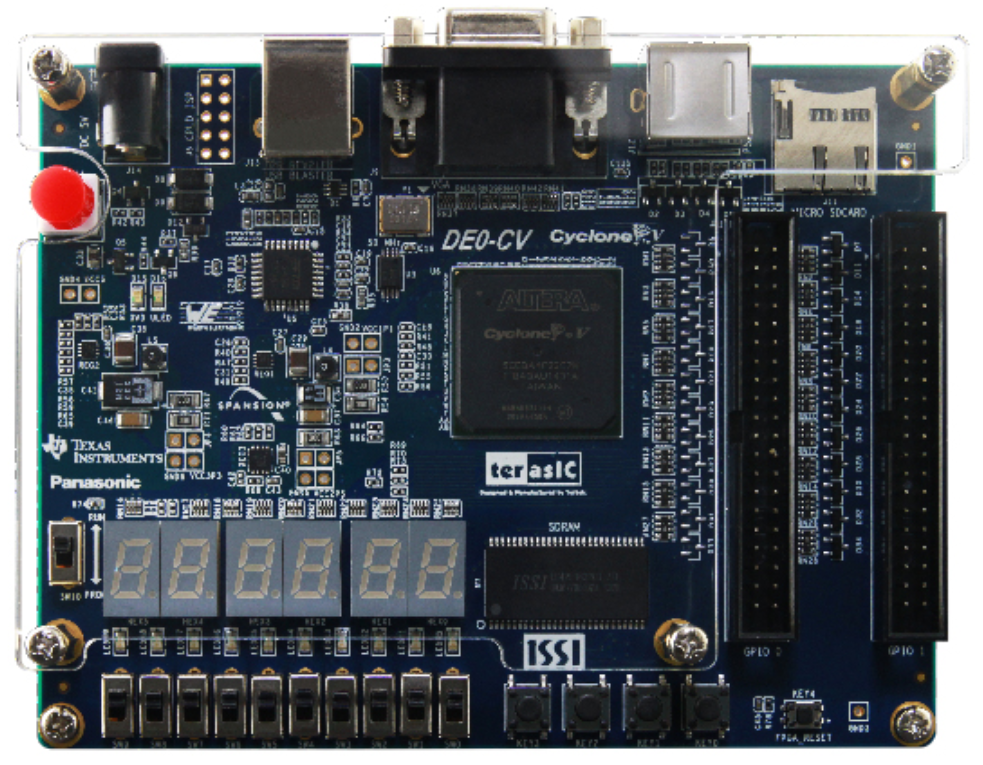
The FPGA Cyclone 5 is a low-cost, low-power field-programmable gate array (FPGA) designed by Intel. It is widely used in applications such as digital signal processing, embedded systems, and high-performance computing. The Cyclone 5 series offers a flexible architecture, high-speed I/O capabilities, and compatibility with various design tools, making it an excellent choice for both prototyping and production environments.
Explore Projects Built with FPGA Cyclone 5
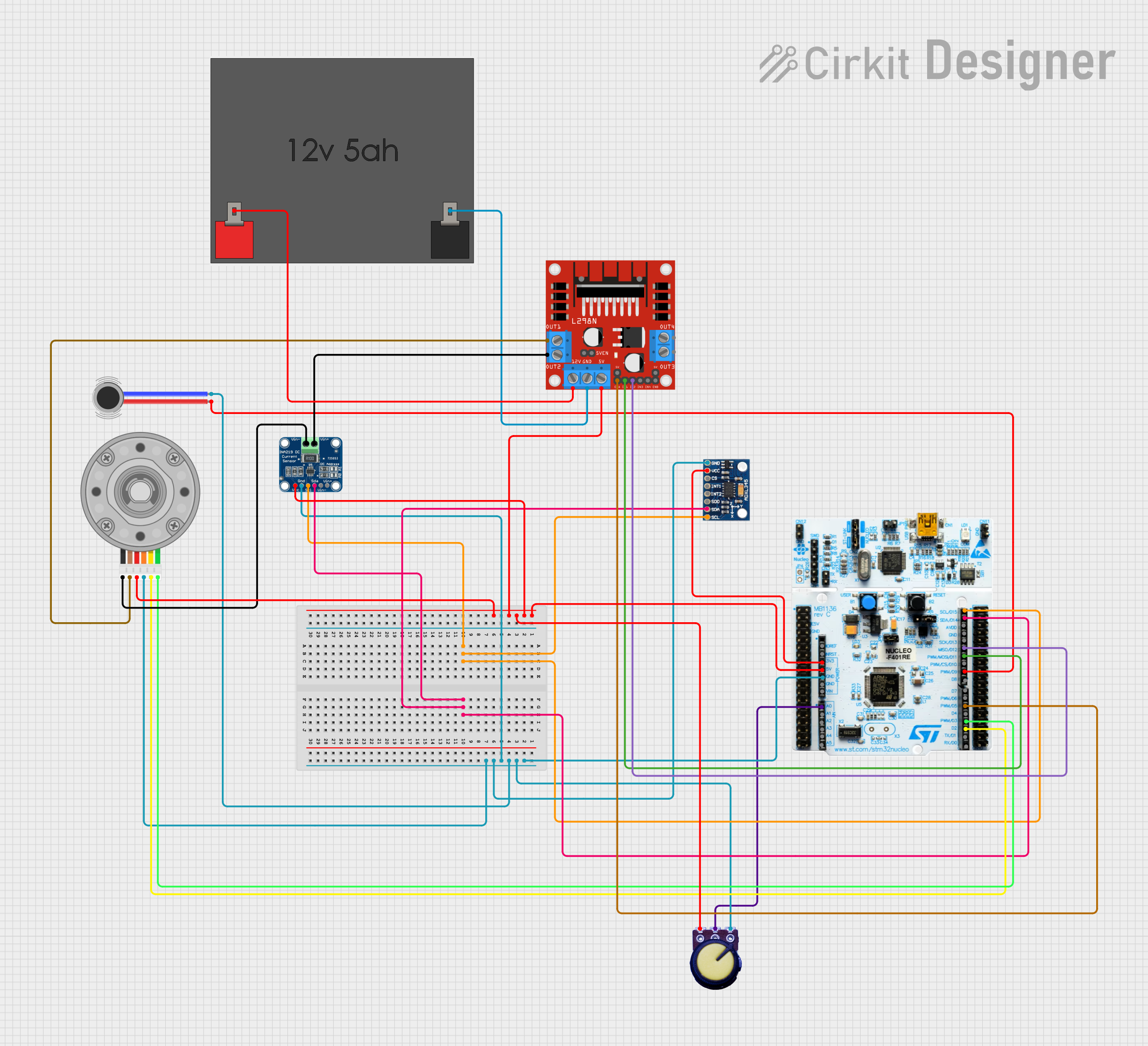
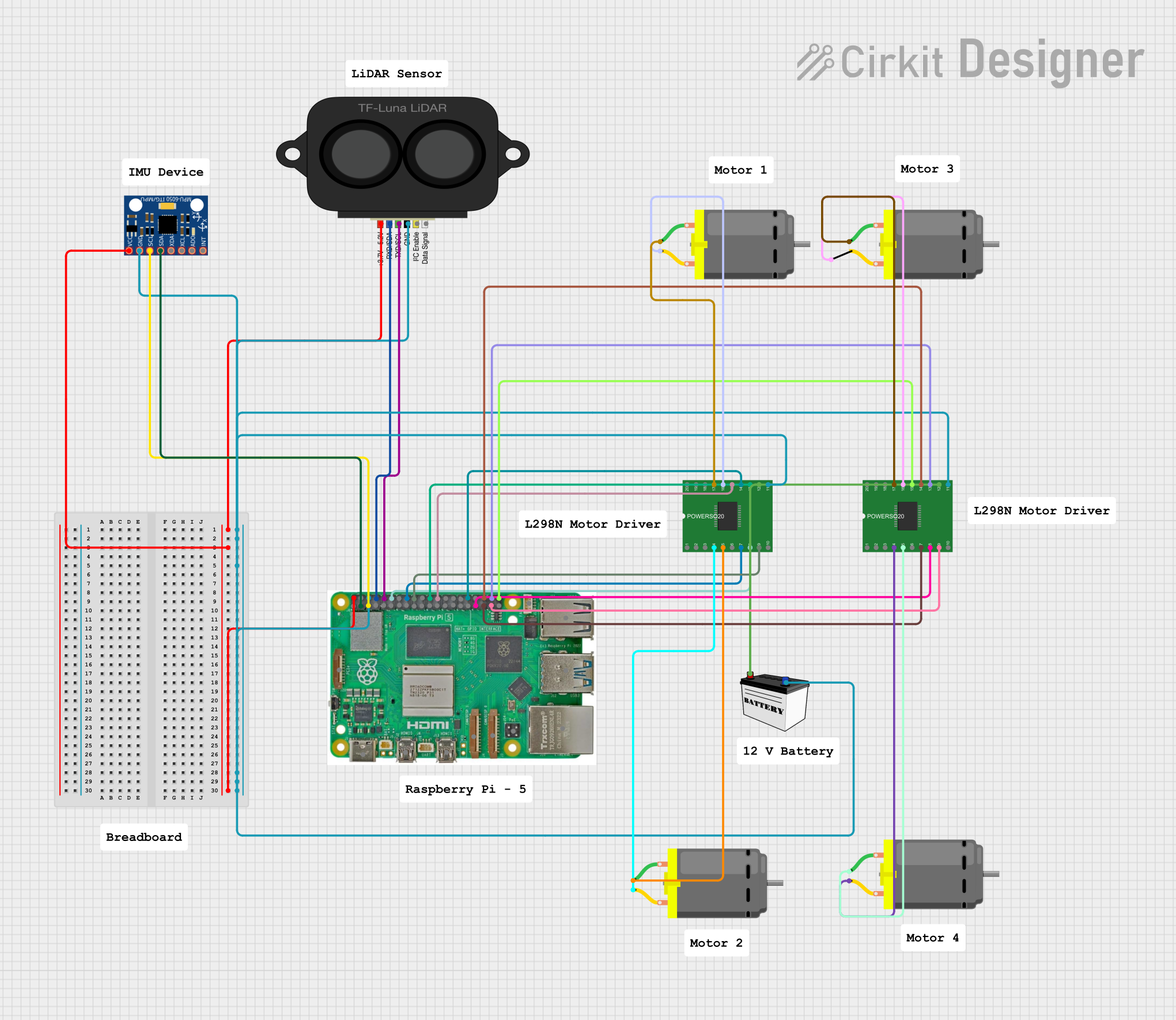

Explore Projects Built with FPGA Cyclone 5
Common Applications and Use Cases
- Digital Signal Processing (DSP): Ideal for real-time signal processing tasks.
- Embedded Systems: Used as a core component in custom embedded designs.
- High-Performance Computing: Suitable for accelerating computationally intensive tasks.
- Industrial Automation: Enables precise control and monitoring in industrial systems.
- IoT Devices: Provides low-power, high-performance solutions for IoT applications.
Technical Specifications
Key Technical Details
- Logic Elements (LEs): Up to 301,000 LEs (depending on the specific model).
- Embedded Memory: Up to 13.1 Mbits of embedded memory.
- Operating Voltage: Core voltage of 1.1V, with I/O voltages ranging from 1.2V to 3.3V.
- Clock Management: Up to 20 phase-locked loops (PLLs) for advanced clocking.
- I/O Pins: Up to 480 user I/O pins.
- Transceivers: High-speed transceivers supporting data rates up to 6.375 Gbps.
- Temperature Range: -40°C to +100°C (industrial-grade models).
- Package Options: Available in various packages, including BGA (Ball Grid Array).
Pin Configuration and Descriptions
The pin configuration of the Cyclone 5 FPGA varies depending on the specific model and package. Below is an example of a typical pin configuration for a Cyclone 5 device in a BGA package:
| Pin Name | Type | Description |
|---|---|---|
| VCCINT | Power | Core voltage supply (1.1V). |
| VCCA | Power | Analog voltage supply for PLLs. |
| GND | Ground | Ground connection. |
| IO_xx | I/O | General-purpose input/output pins. |
| CLKIN | Input | Clock input pin for external clock sources. |
| CONFIG_xx | Configuration | Pins used for FPGA configuration (e.g., JTAG, AS, PS modes). |
| TX/RX_xx | Transceiver | High-speed transceiver pins for serial communication. |
| NC | Not Connected | Pins that are not connected internally (leave unconnected in the design). |
Refer to the specific datasheet for your Cyclone 5 model to obtain the exact pinout and configuration details.
Usage Instructions
How to Use the FPGA Cyclone 5 in a Circuit
Power Supply:
- Provide a stable 1.1V core voltage to the VCCINT pins.
- Ensure proper decoupling capacitors are placed near the power pins to reduce noise.
- Supply appropriate I/O voltages (1.2V to 3.3V) based on the connected peripherals.
Clocking:
- Connect an external clock source to the CLKIN pin or use the internal PLLs for clock generation.
- Configure the clock frequency and phase using Intel's Quartus Prime software.
Configuration:
- Choose a configuration mode (e.g., JTAG, Active Serial (AS), Passive Serial (PS)).
- Use a USB-Blaster or similar programmer to load the bitstream file into the FPGA.
I/O Connections:
- Assign I/O pins in the Quartus Prime software based on your design requirements.
- Use appropriate level shifters if interfacing with devices operating at different voltage levels.
Programming:
- Design your logic circuit using Verilog or VHDL in Quartus Prime.
- Compile the design to generate a bitstream file (.sof or .pof).
- Program the FPGA using the selected configuration mode.
Important Considerations and Best Practices
- Thermal Management: Ensure adequate cooling (e.g., heat sinks or fans) for high-performance designs.
- Signal Integrity: Use proper PCB design practices, such as controlled impedance traces, for high-speed signals.
- Power Sequencing: Follow the recommended power-up and power-down sequencing to avoid damage.
- Debugging: Use the SignalTap Logic Analyzer in Quartus Prime for real-time debugging of your design.
Example: Interfacing Cyclone 5 with Arduino UNO
While the Cyclone 5 FPGA is not directly compatible with Arduino UNO due to voltage and complexity differences, it can communicate with Arduino via level shifters and serial communication. Below is an example of Arduino code to send data to the FPGA via UART:
// Arduino UNO UART Communication with Cyclone 5 FPGA
// Ensure a level shifter is used to match voltage levels between Arduino (5V)
// and the FPGA (3.3V).

void setup() {
  Serial.begin(9600); // Initialize UART communication at 9600 baud rate
  delay(1000);        // Wait for the FPGA to initialize
}

void loop() {
  Serial.println("Hello FPGA!"); // Send a test message to the FPGA
  delay(1000);                  // Wait 1 second before sending the next message
}
On the FPGA side, you can implement a UART receiver module in Verilog or VHDL to process the incoming data.
Troubleshooting and FAQs
Common Issues and Solutions
FPGA Not Powering On:
- Cause: Incorrect power supply or missing decoupling capacitors.
- Solution: Verify the power supply voltages and ensure proper decoupling.
Configuration Fails:
- Cause: Incorrect configuration mode or faulty programmer.
- Solution: Check the configuration mode settings and ensure the programmer is functioning correctly.
High-Speed Transceiver Errors:
- Cause: Poor signal integrity or incorrect termination.
- Solution: Use proper PCB design practices and verify termination resistors.
Overheating:
- Cause: Insufficient cooling for high-performance designs.
- Solution: Add heat sinks or fans to manage thermal dissipation.
FAQs
Q: Can I use Cyclone 5 for machine learning applications?
A: Yes, Cyclone 5 can be used for machine learning inference tasks, especially for low-power applications.Q: What software tools are compatible with Cyclone 5?
A: Intel Quartus Prime is the primary design tool for Cyclone 5. It supports design entry, simulation, and programming.Q: How do I debug my design on Cyclone 5?
A: Use the SignalTap Logic Analyzer in Quartus Prime to monitor internal signals in real time.Q: Can Cyclone 5 interface with 5V devices?
A: No, Cyclone 5 operates at 3.3V or lower. Use level shifters to interface with 5V devices.
By following this documentation, you can effectively utilize the FPGA Cyclone 5 in your projects. For more detailed information, refer to the official Intel Cyclone 5 datasheet and user guide.