
How to Use ZK-MT21: Examples, Pinouts, and Specs
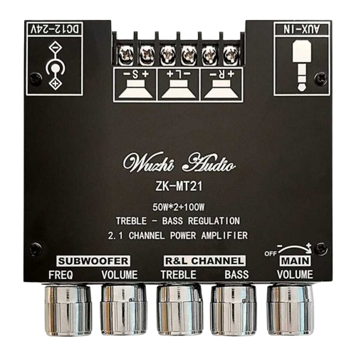
 Design with ZK-MT21 in Cirkit Designer
Introduction
The ZK-MT21 is a compact, high-performance microcontroller designed for embedded applications. It is engineered to deliver low power consumption while offering a variety of I/O interfaces, making it suitable for versatile connectivity. This microcontroller is ideal for applications such as IoT devices, home automation, robotics, and industrial control systems. Its small form factor and robust feature set make it a popular choice for developers seeking efficiency and flexibility in their designs.
Explore Projects Built with ZK-MT21
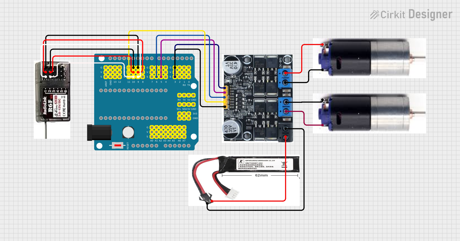
 Open Project in Cirkit Designer
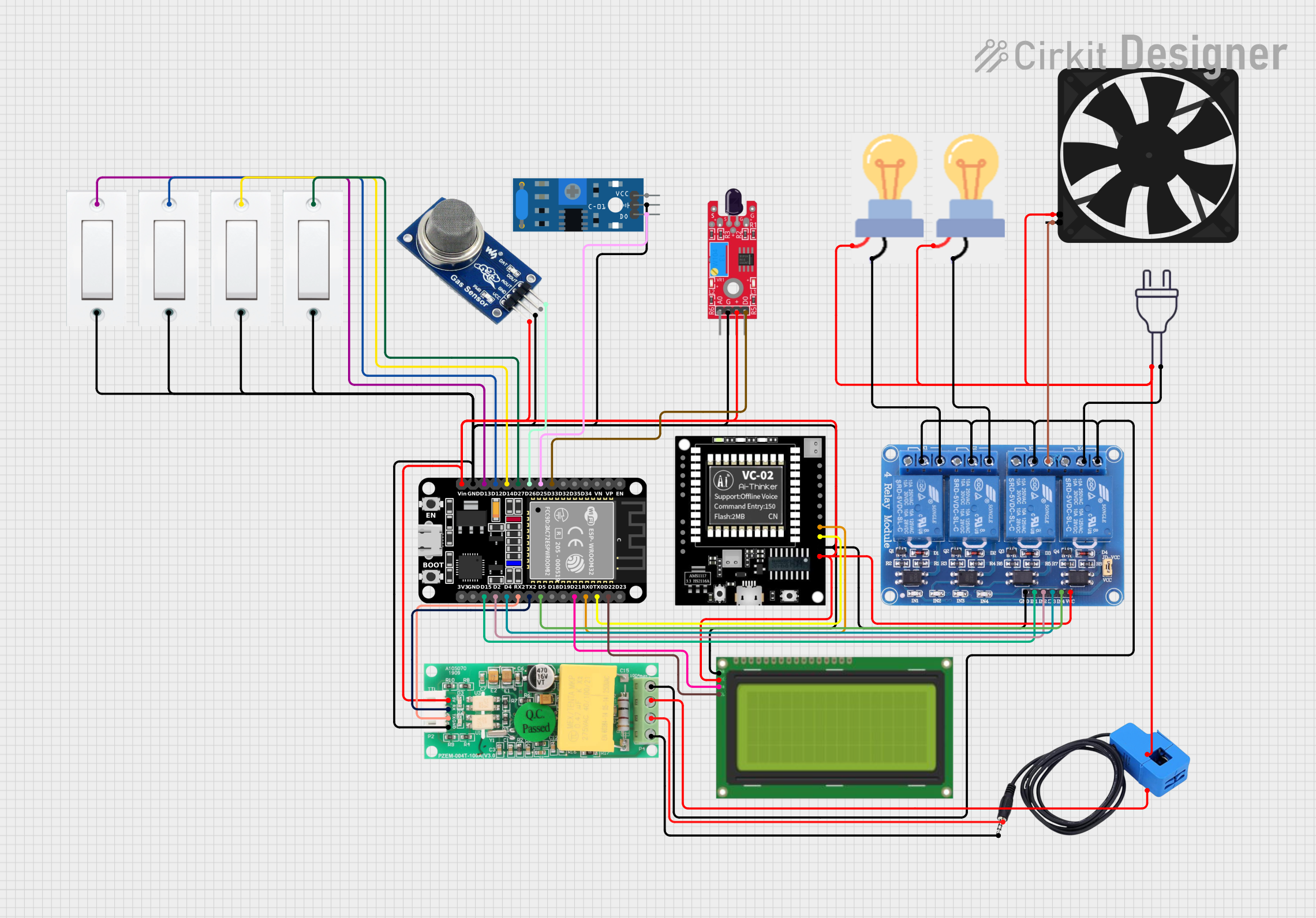
 Open Project in Cirkit Designer
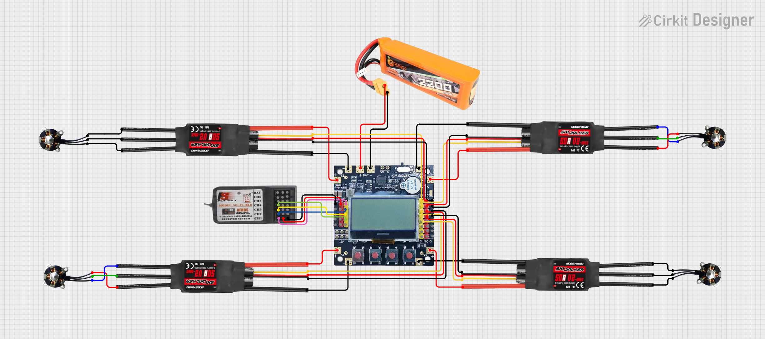
 Open Project in Cirkit Designer
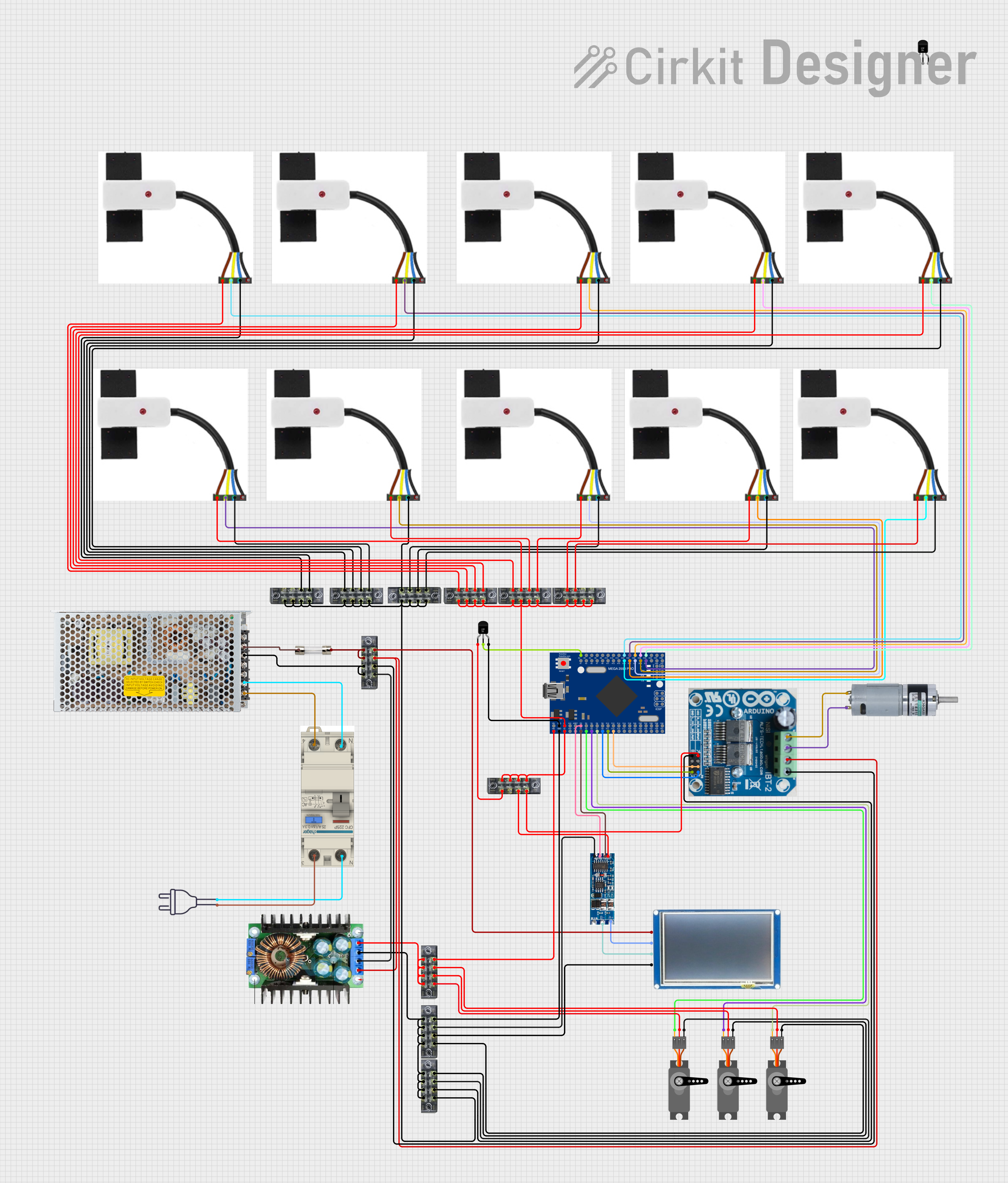
 Open Project in Cirkit Designer
Explore Projects Built with ZK-MT21

 Open Project in Cirkit Designer
 Open Project in Cirkit Designer
 Open Project in Cirkit Designer
 Open Project in Cirkit Designer
Technical Specifications
The ZK-MT21 microcontroller is equipped with the following key technical features:
General Specifications
- Core: 32-bit RISC processor
- Operating Voltage: 3.3V
- Clock Speed: Up to 48 MHz
- Flash Memory: 64 KB
- SRAM: 8 KB
- GPIO Pins: 20 configurable pins
- Communication Interfaces: UART, SPI, I2C
- ADC Resolution: 10-bit, 6 channels
- Power Consumption: Ultra-low power mode < 1 µA
- Package Type: QFN-32
Pin Configuration and Descriptions
The ZK-MT21 features a 32-pin QFN package. Below is the pin configuration:
| Pin Number | Pin Name | Description |
|---|---|---|
| 1 | VDD | Power supply (3.3V) |
| 2 | GND | Ground |
| 3 | GPIO1 | General-purpose I/O pin 1 |
| 4 | GPIO2 | General-purpose I/O pin 2 |
| 5 | UART_TX | UART Transmit |
| 6 | UART_RX | UART Receive |
| 7 | SPI_MOSI | SPI Master Out Slave In |
| 8 | SPI_MISO | SPI Master In Slave Out |
| 9 | SPI_SCK | SPI Clock |
| 10 | SPI_CS | SPI Chip Select |
| 11 | I2C_SDA | I2C Data Line |
| 12 | I2C_SCL | I2C Clock Line |
| 13-18 | ADC1-ADC6 | Analog-to-Digital Converter inputs |
| 19-30 | GPIO3-GPIO14 | General-purpose I/O pins |
| 31 | RESET | Reset pin |
| 32 | NC | Not connected |
Usage Instructions
How to Use the ZK-MT21 in a Circuit
- Power Supply: Connect the VDD pin to a 3.3V power source and the GND pin to ground.
- GPIO Configuration: Configure the GPIO pins as input or output based on your application. Use pull-up or pull-down resistors if necessary.
- Communication Interfaces:
- For UART communication, connect the UART_TX and UART_RX pins to the corresponding pins of your device.
- For SPI, connect SPI_MOSI, SPI_MISO, SPI_SCK, and SPI_CS to the SPI bus.
- For I2C, connect I2C_SDA and I2C_SCL to the I2C bus with appropriate pull-up resistors (typically 4.7 kΩ).
- ADC Usage: Connect analog sensors to the ADC pins (ADC1-ADC6) for data acquisition.
- Reset: Use the RESET pin to restart the microcontroller if needed.
Important Considerations and Best Practices
- Ensure the operating voltage does not exceed 3.3V to prevent damage to the microcontroller.
- Use decoupling capacitors (e.g., 0.1 µF) near the VDD pin to stabilize the power supply.
- Avoid leaving unused GPIO pins floating; configure them as inputs with pull-up or pull-down resistors.
- For low-power applications, utilize the ultra-low power mode to conserve energy.
Example: Connecting ZK-MT21 to an Arduino UNO
The ZK-MT21 can be interfaced with an Arduino UNO via UART. Below is an example Arduino sketch to communicate with the ZK-MT21:
// Example: Arduino UNO communicating with ZK-MT21 via UART
// Ensure the ZK-MT21's UART_TX is connected to Arduino's RX (pin 0)
// and UART_RX is connected to Arduino's TX (pin 1).

void setup() {
  Serial.begin(9600); // Initialize UART communication at 9600 baud rate
  delay(1000);        // Wait for the ZK-MT21 to initialize
  Serial.println("Hello, ZK-MT21!"); // Send a message to the ZK-MT21
}

void loop() {
  if (Serial.available()) { // Check if data is received from ZK-MT21
    String data = Serial.readString(); // Read the incoming data
    Serial.println("Received: " + data); // Print the received data
  }
  delay(500); // Add a delay to avoid flooding the serial monitor
}
Troubleshooting and FAQs
Common Issues and Solutions
Microcontroller Not Powering On:
- Ensure the VDD pin is connected to a stable 3.3V power source.
- Check for loose connections or damaged wires.
No Communication via UART:
- Verify the baud rate settings match between the ZK-MT21 and the connected device.
- Ensure the UART_TX and UART_RX pins are correctly connected.
ADC Not Reading Correctly:
- Confirm the input voltage to the ADC pins is within the 0-3.3V range.
- Check for noise or instability in the analog signal.
GPIO Pins Not Responding:
- Ensure the pins are correctly configured as input or output in your code.
- Check for short circuits or incorrect wiring.
FAQs
Q: Can the ZK-MT21 operate at 5V?
A: No, the ZK-MT21 is designed to operate at 3.3V. Using 5V may damage the microcontroller.Q: How do I update the firmware on the ZK-MT21?
A: Firmware updates can be performed via the UART interface using a compatible bootloader.Q: What is the maximum clock speed of the ZK-MT21?
A: The ZK-MT21 supports a maximum clock speed of 48 MHz.Q: Can I use all GPIO pins simultaneously?
A: Yes, but ensure the total current draw does not exceed the microcontroller's limits.
By following this documentation, you can effectively integrate the ZK-MT21 into your projects and troubleshoot common issues.