
How to Use SWITCH-DPDT: Examples, Pinouts, and Specs
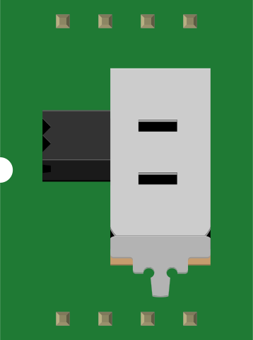
 Design with SWITCH-DPDT in Cirkit Designer
Introduction
A Double Pole Double Throw (DPDT) switch is an electrical switch designed to control two separate circuits simultaneously. It features two input terminals and can connect each input to one of two output terminals, effectively allowing for two different outputs. This versatility makes the DPDT switch a popular choice in applications requiring circuit selection, polarity reversal, or motor control.
Explore Projects Built with SWITCH-DPDT
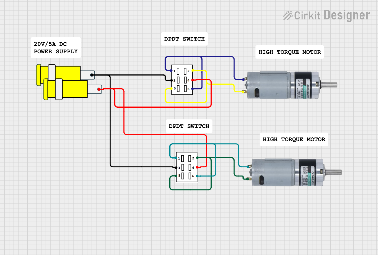 Open Project in Cirkit Designer
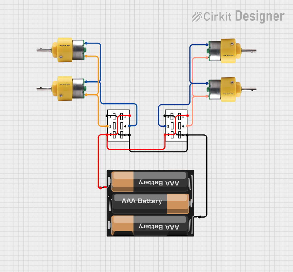 Open Project in Cirkit Designer
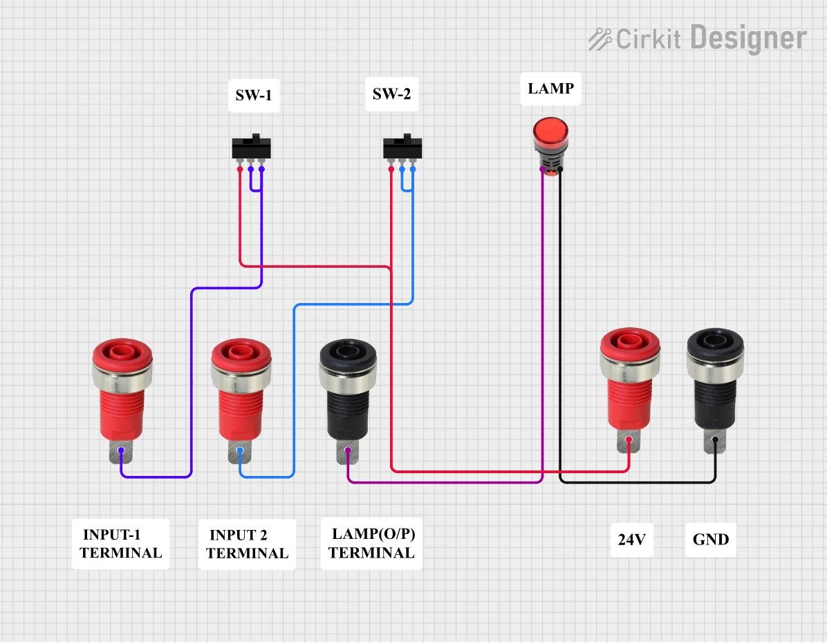 Open Project in Cirkit Designer
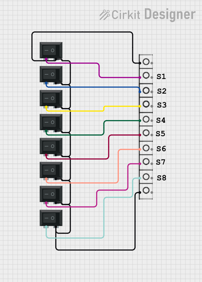 Open Project in Cirkit Designer
Explore Projects Built with SWITCH-DPDT
Open Project in Cirkit DesignerOpen Project in Cirkit DesignerOpen Project in Cirkit DesignerOpen Project in Cirkit DesignerCommon Applications and Use Cases
- Polarity reversal for DC motors
- Switching between two power sources
- Audio signal routing
- Controlling two independent circuits with a single switch
- Applications requiring ON-ON or ON-OFF-ON configurations
Technical Specifications
Below are the key technical details for a standard DPDT switch:
| Parameter | Value |
|---|---|
| Voltage Rating | Typically 12V to 250V AC/DC |
| Current Rating | 1A to 15A (varies by model) |
| Contact Configuration | Double Pole Double Throw (DPDT) |
| Operating Modes | ON-ON or ON-OFF-ON |
| Mechanical Life | 10,000 to 50,000 cycles |
| Mounting Style | Panel mount or PCB mount |
Pin Configuration and Descriptions
A DPDT switch typically has six terminals. The pin configuration is as follows:
| Pin Number | Label | Description |
|---|---|---|
| 1 | Input 1 (Pole 1) | First input terminal for the first circuit |
| 2 | Output 1A | First output terminal for the first circuit |
| 3 | Output 1B | Second output terminal for the first circuit |
| 4 | Input 2 (Pole 2) | Second input terminal for the second circuit |
| 5 | Output 2A | First output terminal for the second circuit |
| 6 | Output 2B | Second output terminal for the second circuit |
Usage Instructions
How to Use the DPDT Switch in a Circuit
- Identify the Terminals: Locate the six terminals on the switch. Refer to the pin configuration table above to understand their functions.
- Connect the Inputs: Attach the two input terminals (Pin 1 and Pin 4) to the respective power sources or circuits you wish to control.
- Connect the Outputs: Connect the output terminals (Pins 2, 3, 5, and 6) to the devices or circuits you want to control.
- Switch Operation: Toggle the switch to change the connection between the inputs and outputs. In an ON-ON configuration, the switch alternates between two output states. In an ON-OFF-ON configuration, the middle position disconnects the outputs.
Important Considerations and Best Practices
- Voltage and Current Ratings: Ensure the switch's voltage and current ratings match your circuit requirements to avoid damage.
- Debouncing: When using the switch in digital circuits, consider implementing debouncing techniques to eliminate noise caused by mechanical contacts.
- Mounting: Securely mount the switch to prevent accidental disconnections or damage.
- Polarity Reversal: For DC motor control, connect the DPDT switch in an H-bridge configuration to reverse the motor's direction.
Example: Using a DPDT Switch with an Arduino UNO
Below is an example of using a DPDT switch to control the direction of a DC motor with an Arduino UNO:
// Example: Controlling a DC motor's direction using a DPDT switch and Arduino UNO

const int motorPin1 = 9; // Pin connected to one side of the motor
const int motorPin2 = 10; // Pin connected to the other side of the motor
const int switchPin = 2; // Pin connected to the DPDT switch

void setup() {
  pinMode(motorPin1, OUTPUT); // Set motorPin1 as output
  pinMode(motorPin2, OUTPUT); // Set motorPin2 as output
  pinMode(switchPin, INPUT_PULLUP); // Set switchPin as input with pull-up resistor
}

void loop() {
  int switchState = digitalRead(switchPin); // Read the state of the DPDT switch

  if (switchState == LOW) {
    // If the switch is in one position, rotate motor in one direction
    digitalWrite(motorPin1, HIGH); // Set motorPin1 HIGH
    digitalWrite(motorPin2, LOW);  // Set motorPin2 LOW
  } else {
    // If the switch is in the other position, reverse motor direction
    digitalWrite(motorPin1, LOW);  // Set motorPin1 LOW
    digitalWrite(motorPin2, HIGH); // Set motorPin2 HIGH
  }
}
Troubleshooting and FAQs
Common Issues Users Might Face
Switch Not Functioning Properly:
- Cause: Incorrect wiring or loose connections.
- Solution: Double-check the wiring and ensure all connections are secure.
Overheating:
- Cause: Exceeding the switch's voltage or current rating.
- Solution: Verify that the switch's ratings match your circuit requirements.
Noise or Flickering in Digital Circuits:
- Cause: Mechanical contact bounce.
- Solution: Implement software or hardware debouncing techniques.
Motor Not Reversing Direction:
- Cause: Incorrect wiring of the DPDT switch in the H-bridge configuration.
- Solution: Verify the connections and ensure the switch is wired correctly.
FAQs
Q1: Can I use a DPDT switch to control AC circuits?
A1: Yes, as long as the switch's voltage and current ratings are suitable for the AC circuit.
Q2: What is the difference between ON-ON and ON-OFF-ON configurations?
A2: In an ON-ON configuration, the switch alternates between two output states. In an ON-OFF-ON configuration, the middle position disconnects the outputs.
Q3: How do I debounce a DPDT switch in software?
A3: Use a delay or a state-change detection algorithm in your microcontroller code to filter out noise caused by mechanical bouncing.
Q4: Can I use a DPDT switch for audio signal routing?
A4: Yes, DPDT switches are commonly used to route audio signals between different outputs or inputs.