How to Use Adafruit Feather M0 WINC1500: Examples, Pinouts, and Specs
Introduction
The Adafruit Feather M0 WINC1500 is a powerful, Wi-Fi enabled development board that combines the benefits of the ATSAMD21G18 ARM Cortex M0 processor with the ATWINC1500 Wi-Fi module. This board is part of the Feather ecosystem, designed for portability, ease of use, and rapid development. It is ideal for Internet of Things (IoT) projects, remote sensor networks, and any application requiring wireless data communication.
Explore Projects Built with Adafruit Feather M0 WINC1500

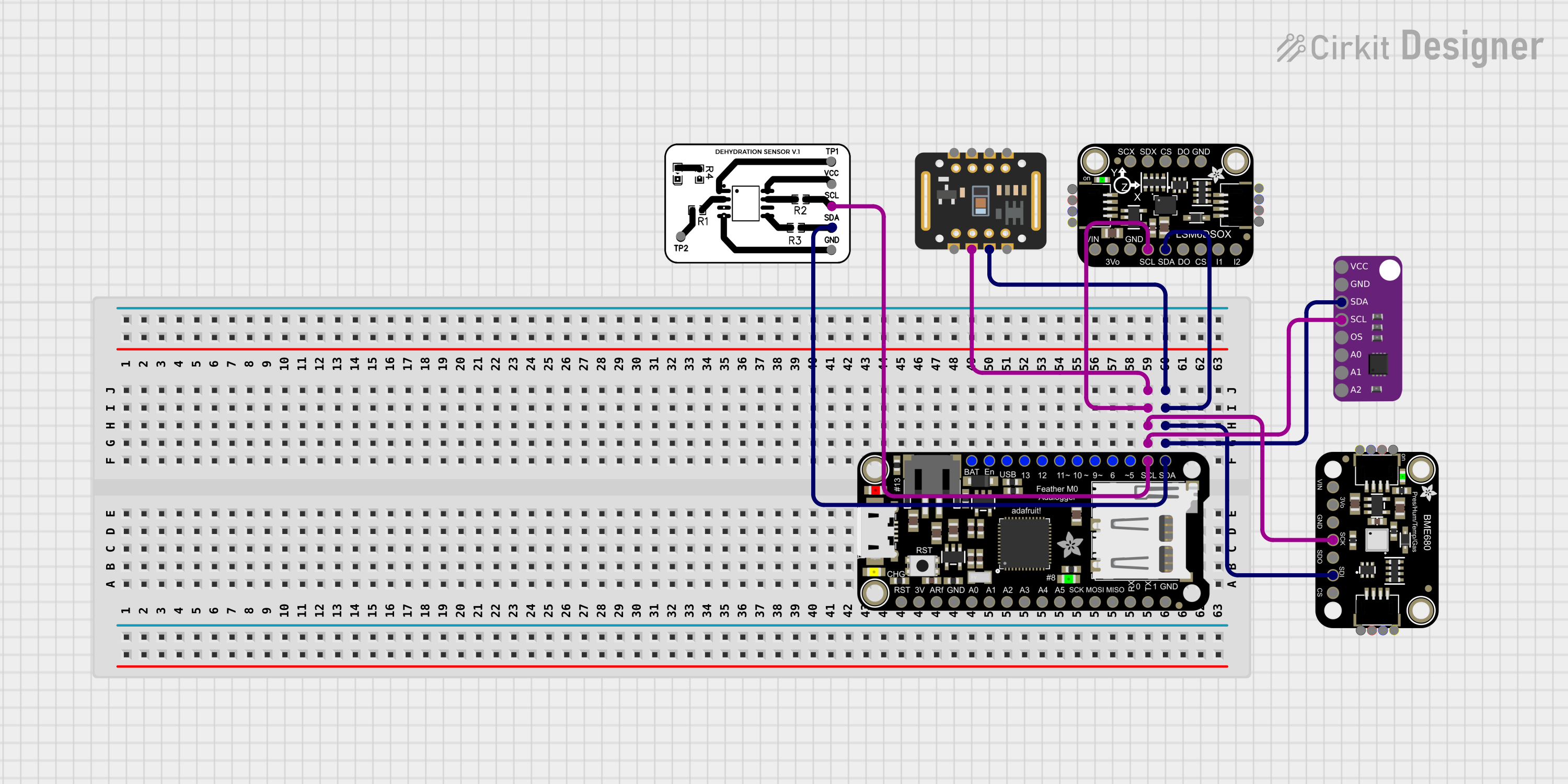
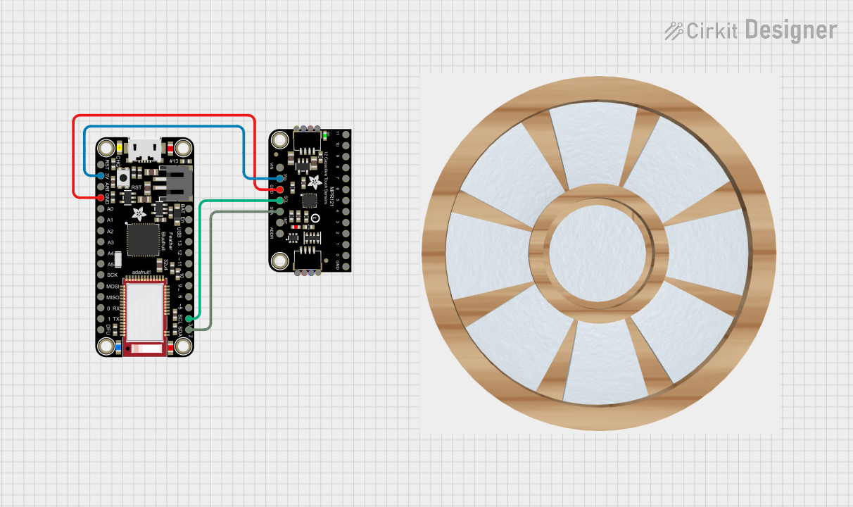
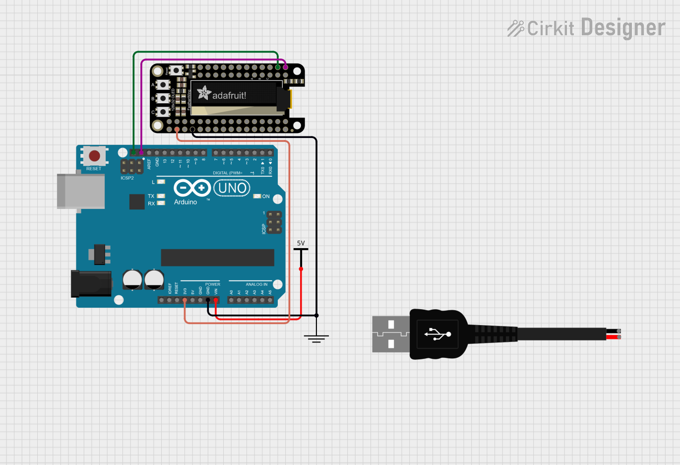
Explore Projects Built with Adafruit Feather M0 WINC1500
Common Applications and Use Cases
- IoT devices
- Wireless data loggers
- Remote sensors and controllers
- Home automation
- Wearable electronics
Technical Specifications
Key Technical Details
- Microcontroller: ATSAMD21G18, 32-bit ARM Cortex M0+
- Operating Voltage: 3.3V
- Input Voltage: 3.7-6V via battery and USB, 5V via USB
- Digital I/O Pins: 20
- PWM Channels: 12
- Analog Input Channels: 6 (12-bit ADC)
- Analog Output Channels: 1 (10-bit DAC)
- Flash Memory: 256KB
- SRAM: 32KB
- Clock Speed: 48 MHz
- Wi-Fi Module: ATWINC1500 802.11 b/g/n
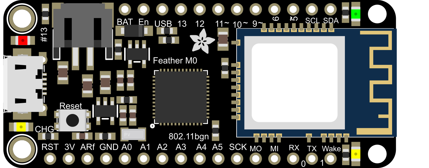
Pin Configuration and Descriptions
| Pin Number | Function | Description |
|---|---|---|
| 1 | GND | Ground |
| 2 | 3V3 | 3.3V output from the regulator |
| 3 | BAT | Battery voltage (for battery-powered setups) |
| 4 | EN | Enable pin for the regulator |
| 5 | USB | USB power (5V from USB port) |
| 6-17 | Digital Pins | Digital input/output pins |
| 18-23 | Analog Pins | Analog input pins |
| 24 | AREF | Analog reference voltage |
| 25 | SCK | SPI clock |
| 26 | MISO | SPI Master In Slave Out |
| 27 | MOSI | SPI Master Out Slave In |
| 28 | RX | UART receive |
| 29 | TX | UART transmit |
| 30 | SDA | I2C data |
| 31 | SCL | I2C clock |
Usage Instructions
How to Use the Component in a Circuit
Powering the Board:
- Connect a 3.7V Lithium polymer battery to the JST connector for portable applications.
- Use the USB connection for development and when a battery is not required.
Connecting to Wi-Fi:
- Ensure that the antenna on the WINC1500 module is not obstructed.
- Use the provided libraries to connect to a Wi-Fi network.
Programming the Board:
- Use the Arduino IDE with the appropriate board package installed.
- Select "Adafruit Feather M0" from the board menu.
Important Considerations and Best Practices
- Always disconnect the battery before soldering to the board.
- Avoid exposing the board to static electricity to prevent damage.
- Ensure that the input voltage does not exceed the recommended range to avoid damaging the voltage regulator.
- When using Wi-Fi, consider the power consumption and ensure that your power source can provide sufficient current.
Troubleshooting and FAQs
Common Issues
Wi-Fi Connection Failure:
- Check the SSID and password.
- Ensure the Wi-Fi network is within range.
- Restart the board and try connecting again.
Board Not Recognized by Computer:
- Use a different USB cable and port.
- Ensure the board drivers are installed correctly.
- Press the reset button twice quickly to enter bootloader mode.
Solutions and Tips for Troubleshooting
Updating Firmware:
- Occasionally, the Wi-Fi module may require a firmware update. Follow the instructions provided by Adafruit to update the firmware.
Power Issues:
- If the board is unresponsive, check the battery and USB connections for proper voltage levels.
FAQs
Can I use the Feather M0 WINC1500 with a battery and USB at the same time?
- Yes, the board includes a charging circuit for the battery when powered via USB.
What libraries do I need for Wi-Fi functionality?
- Use the Adafruit_WINC1500 library available through the Arduino Library Manager.
Example Code for Arduino UNO
Below is a simple example code that connects the Adafruit Feather M0 WINC1500 to a Wi-Fi network. Ensure you have the Adafruit_WINC1500 library installed before uploading this sketch.
#include <SPI.h>
#include <WiFi101.h>

char ssid[] = "your_network";     // your network SSID (name)
char pass[] = "secret_password";  // your network password

int status = WL_IDLE_STATUS;

void setup() {
  // Initialize serial and wait for the port to open:
  Serial.begin(9600);
  while (!Serial) {
    ; // wait for serial port to connect. Needed for native USB port only
  }

  // Check for the presence of the shield:
  if (WiFi.status() == WL_NO_SHIELD) {
    Serial.println("WiFi shield not present");
    // Don't continue:
    while (true);
  }

  // Attempt to connect to Wi-Fi network:
  while (status != WL_CONNECTED) {
    Serial.print("Attempting to connect to SSID: ");
    Serial.println(ssid);
    // Connect to WPA/WPA2 network:
    status = WiFi.begin(ssid, pass);

    // Wait 10 seconds for connection:
    delay(10000);
  }

  Serial.println("Connected to wifi");
  printWifiStatus();
}

void loop() {
  // Nothing here for now.
}

void printWifiStatus() {
  // Print the SSID of the network you're attached to:
  Serial.print("SSID: ");
  Serial.println(WiFi.SSID());

  // Print your board's IP address:
  IPAddress ip = WiFi.localIP();
  Serial.print("IP Address: ");
  Serial.println(ip);

  // Print the received signal strength:
  long rssi = WiFi.RSSI();
  Serial.print("Signal strength (RSSI):");
  Serial.print(rssi);
  Serial.println(" dBm");
}
Remember to replace your_network and secret_password with your actual Wi-Fi network name and password. This code initializes the Wi-Fi module and attempts to connect to the specified network, printing the connection status to the Serial Monitor.